RAK2305 WisBlock Wireless Module Quick Start Guide
Prerequisites
What Do You Need?
Before going through each and every step on using the RAK2305 WisBlock Wireless Module, make sure to prepare the necessary items listed below:
Hardware
- RAK2305 WisBlock Wireless Module
- Your choice of WisBlock Base
- Your choice of WisBlock Core
- USB Cable
- Li-Ion/LiPo battery (optional)
- Solar charger (optional)
- USB to UART TTL adapter(to flash image)
- Jumper (to flash image)
Software
ESP-AT project
ESP-AT is a project developed by Espressif to integrate connectivity into customers’ products. It aims to reduce software development costs and allows you to create new products quickly. AT is the abbreviation for Attention. These commands come from Hayes commands that were used by the Hayes smart modems.
ESP-AT is based on ESP-IDF, the official development framework for the ESP32. On this solution, a WisBlock Core works as an Initiator and the WisBlock Wireless RAK2305 is the target. The initiator sends AT commands via UART to the target and receives AT responses back. The AT commands are processed on target one by one. Therefore, you should wait for the previous command to be executed before sending out the next one. You can develop your own AT commands based on the ESP-AT project and implement more features according to your needs. Check the Low Level Development section.
Two RAK2305 ESP-AT firmware versions are available:
- RAK2305-Basic-WIFI-BLE-AT.bin:The Factory bin version with WiFi and BLE AT commands. This is the default firmware uploaded to the RAK2305.
- RAK2305-Basic-WIFI-HTTP-MQTT-AT.bin: With WiFi, MQTT and HTTP AT Commands. If you want to use the MQTT and HTTP AT Commands, this firmware is needed.
Product Configuration
Hardware Setup
RAK2305 WisBlock WiFi Interface Module can only be connected with WisBlock Base Board through the IO SLOT. The IO SLOT is used by the RAK2305 to communicate with the WisBlock Core. Also, always secure the connection of the WisBlock module by using the compatible screws.
For more information about the RAK2305, refer to the Datasheet.
 Figure 1: RAK2305 connection to WisBlock Base
Assembling and Disassembling of WisBlock Modules
Assembling
There is only a single IO SLOT in the WisBlock Base Board to connect the RAK2305. As shown in Figure 2, the location of the slot is properly marked by silkscreen. Follow carefully the procedure defined in RAK5005-O module assembly/disassembly instructions to attach a WisBlock module. Once attached, fix the module with three pieces of M1.2 x 3 mm screws.
 Figure 1: RAK2305 connection to WisBlock Base Board
If you will connect other modules to the remaining WisBlock Base slots, check on the WisBlock Pin Mapper tool for possible conflicts. RAK2305 uses UART communication lines on the IO SLOT.
After all this setup, you can now connect the battery (optional) and USB cable to start programming your WisBlock.
- Battery can cause harm if not handled properly.
- Only 3.7-4.2 V Rechargeable LiPo batteries are supported. It is highly recommended not to use other types of batteries with the system unless you know what you are doing.
- If a non-rechargeable battery is used, it has to be unplugged first before connecting the USB cable to the USB port of the board to configure the device. Not doing so might damage the battery or cause fire.
- Make sure the battery wires match the polarity on the RAK WisBlock Base Board. Not all batteries have the same wiring.
- Only 5 V solar panels are supported. Do not use 12 V solar panels. It will destroy the charging unit and eventually other electronic parts.
Disassembling
- First, remove the screws.
- Once the screws are removed, check the silkscreen of the module to find the correct location where force can be applied. By applying even force under the marked area, the module can be detached from the baseboard.
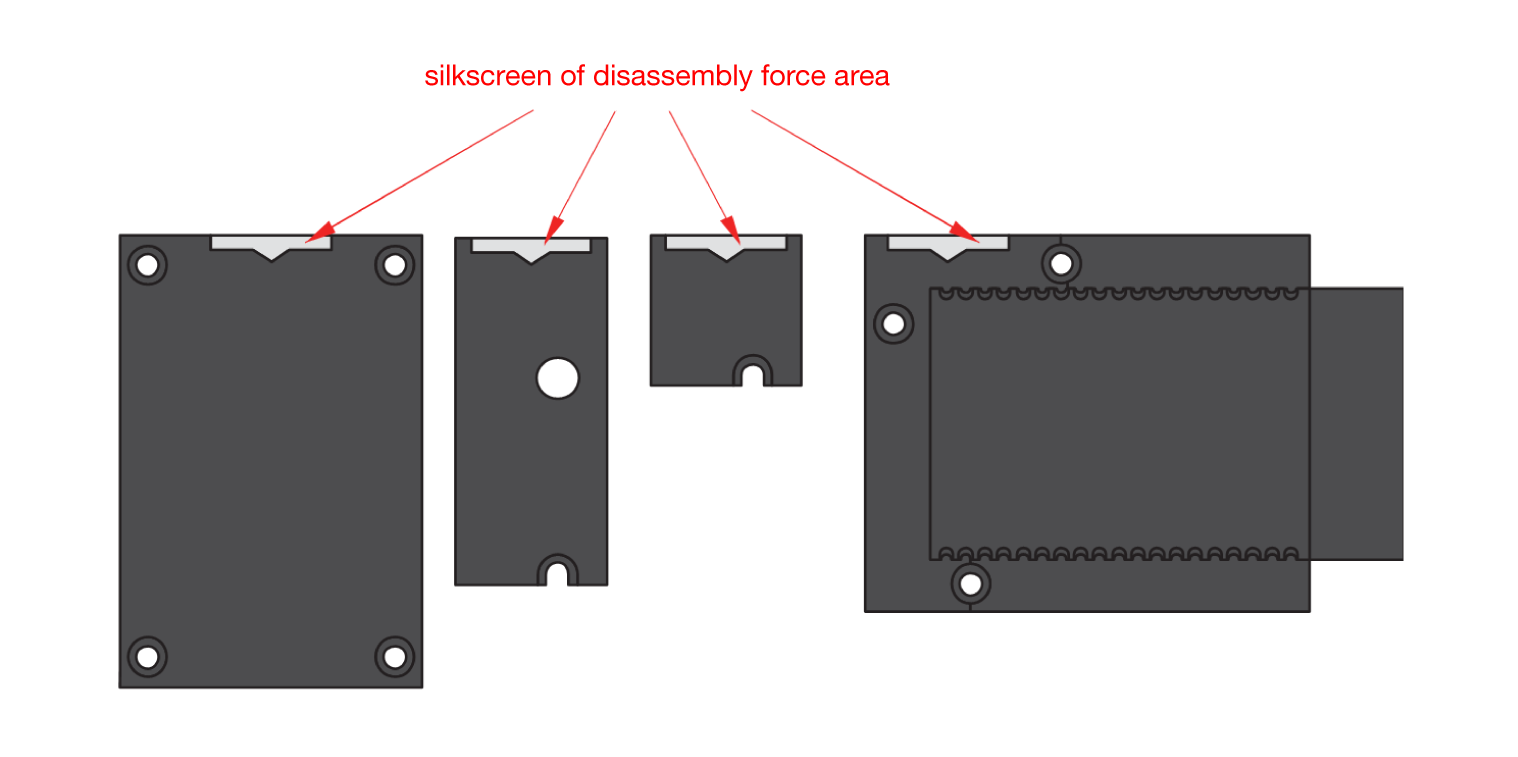 Figure 1: Detaching silkscreen on the WisBlock module
- Apply force to the module at the position of the connector, as shown in Figure 4, to detach the module from the baseboard.
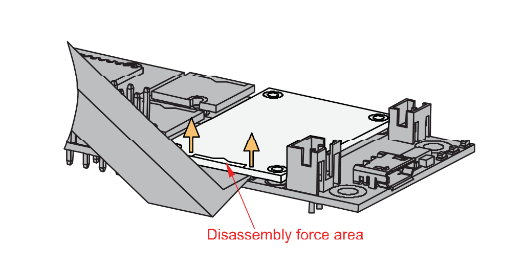 Figure 1: Applying even forces on the proper location of a WisBlock module
Software Configuration and Examples
RAK2305 has a default firmware loaded in it that supports WiFi and BLE related AT Commands. If you need to have HTTP or MQTT functionality, you need to upload a different firmware that supports those features.
The complete list of ESP32 AT Command set can be found in the Espressif AT Command Set online documentation.
Initial Test of the RAK2305 WisBlock Wireless
The AT commands start with AT and end with a new line (CR LF) and the default baud rate of AT Command UART is 115200.
Make sure to use the setup() function with timeout.
void setup()
{
    time_t timeout = millis();
    // Open serial communications and wait for port to open:
    Serial.begin(115200);
    while (!Serial)
    {
        if ((millis() - timeout) < 5000)
        {
            delay(100);
        }
        else
        {
            break;
        }
    }
- First, you need to select the WisBlock Core you have.
Selecting RAK4631 as WisBlock Core.
 Figure 1: Selecting RAK4631 as WisBlock Core
- Then select RAK11310 as WisBlock Core.
 Figure 1: Selecting RAK11310 as WisBlock Core
Examples
For RAK4631 WisBlock Core:
- ESP-AT Command Test - This example waits for an AT command typed at the console. Then sends that command to RAK2305 and wait for reply.
- Connect to Access Point - This example connects to a known access point and send ping to the address "8.8.8.8" every 5 seconds.
For RAK11310 WisBlock Core:
- ESP-AT Command Test - This example waits for an AT command typed at the console then sends that command to RAK2305 and wait for reply.
- Connect to Access Point - This example connects to a known access point and send ping to the address "8.8.8.8" every 5 seconds.
For All WisBlock Core:
The Espressif examples:
Miscellaneous
(Optional) Flashing a Different ESP-AT Firmware into Your Device
To flash the AT firmware, you need a USB to UART TTL adapter like the RAKDAP1 Flash and Debug Tool. Connect the USB adapter to RAK2305, as shown in Figure 5.
 Figure 1: RAK2305 Firmware Upgrade
RAK2305 connection with RAKDAP1:
- USB adapter pin GND connect to RAK2305 GND
- RAK2305 IO0 pin connect to RAK2305 GND (use a jumper)
- USB adapter pin U_TX connect to RAK2305 RXD0 pin
- USB adapter pin U_RX connect to RAK2305 TXD0 pin
Before starting the firmware upgrade, you need to download Flash Download Tools for Windows.
- Open the ESP Flash Download Tool and select ChipType and WorkMode, as shown in Figure 8. Then click the OK button.
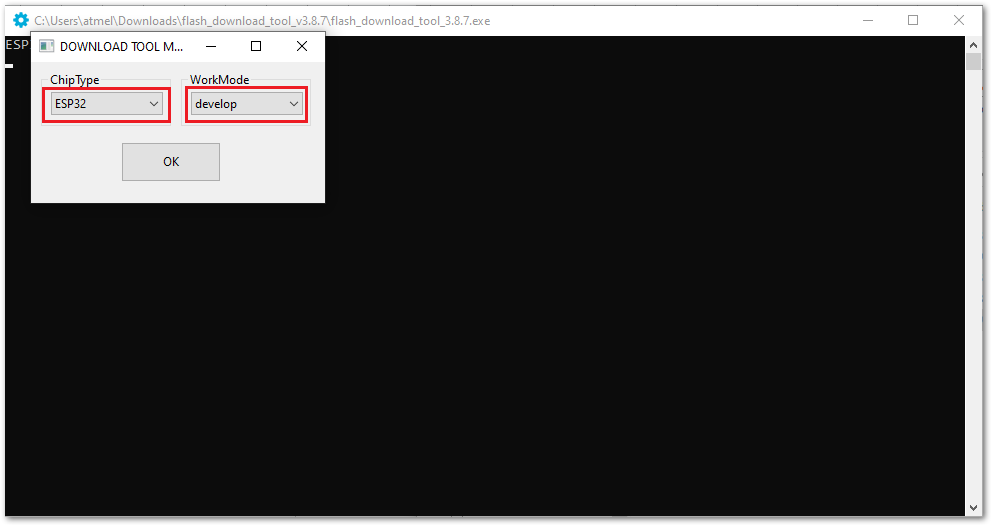 Figure 1: ESP Flash Download Tool
- Choose SPIDownload tab.
- Click on the ... icon and choose the bin file at address 0x0.
- Select DoNotChgBin to use the default configuration.
- Select the COM port of the USB adapter and use 921600 for BAUD.
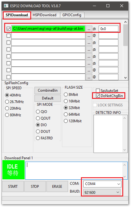 Figure 1: ESP Flash Download Tool Configuration
- To start Flash Download, click on the START button.
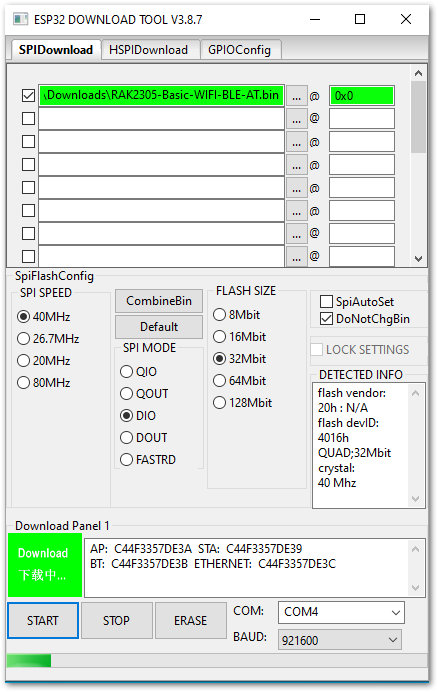 Figure 1: ESP Flash download started
- Download is now finished.
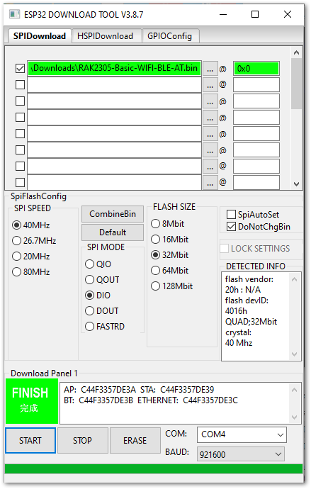 Figure 1: ESP Flash download tool finished