RAK4631-R WisBlock LoRaWAN Module Quick Start Guide
Prerequisite
Package Inclusions
Before going through each step in the installation guide of the RAK4631-R WisBlock Core Module, make sure to prepare the necessary items listed below:
Hardware
- RAK4631-R WisBlock Core
- Your choice of WisBlock Base
- USB Cable
- Li-Ion/LiPo battery (optional)
- Solar charger (optional)
Software
Arduino IDE
- Download and install the Arduino IDE.
If you are using Windows 10. Do NOT install the Arduino IDE from the Microsoft App Store. Instead, install the original Arduino IDE from the Arduino official website. The Arduino app from the Microsoft App Store has problems using third-party Board Support Packages.
- Add RAK4631-R as a supported board in Arduino IDE by updating Board Manager URLs in Preferences settings of Arduino IDE with this JSON URL:
https://raw.githubusercontent.com/RAKWireless/RAKwireless-Arduino-BSP-Index/main/package_rakwireless_com_rui_index.json. - After that, you can then add RAKwireless RUI nRF Boards via Arduino board manager.
Visual Studio IDE
- Download and install the Visual Studio IDE 2019 Community version 16.11.
Product Configuration
Hardware Setup
Your RAK4631-R will not work on its own. It needs at least to be connected to a WisBlock Base together with the antennas attached. You can then interface various WisBlock Modules via the available slots in the WisBlock Base. You can also add a battery as a power source and optional solar charging. All hardware-related configurations for your RAK4631-R are discussed here.
This section covers:
- RAK4631-R Connection to Base Board
- RAK4631-R Connection to Other Modules
- Assembling and Disassembling of WisBlock Modules
- Antenna and Battery/Solar Connection
RAK4631-R to WisBlock Base
The RAK4631-R will not work without a WisBlock Base board. The WisBlock Base provides a USB connection for programming the RAK4631-R. It also provides a power source and various interfaces to RAK4631 so that it can be connected to other WisBlock Modules via different module slots.
RAKwireless offers many WisBlock Base Boards compatible with WisBlock Core. It is highly recommended for you to look at these WisBlock Base boards to see what matches your requirements in terms of available module slots, power supply options, and overall size.
To illustrate, RAK4631-R can be connected to RAK5005-O WisBlock Base, as shown in Figure 1.
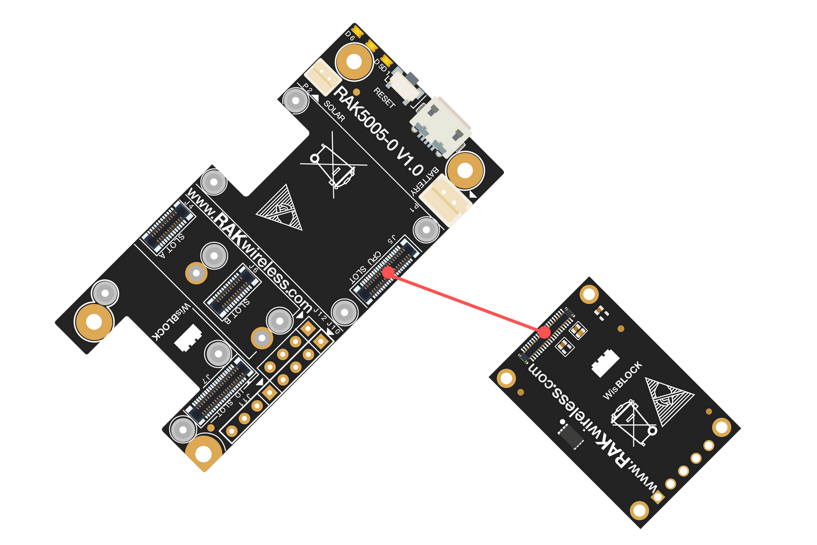 Figure 1: RAK4631-R connection to WisBlock Base RAK5005-O
Few pins are exposed on RAK5005-O, and you can easily use them via header pins. The labels are at the back, as shown in Figure 2.
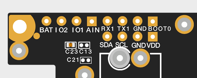 Figure 1: WisBlock Base exposed pins
Each WisBlock Base board has its own set of header pins available for you to use. However, these header pins are not exactly the same in each WisBlock Base. It is common to see IO pins and communication protocol pins like I2C and UART in the WisBlock Base board. More information can be found on the official documentation of the specific WisBlock Base you used in your project.
UART1 of RAK4631-R is also used for DFU (Device Firmware Upgrade) via UART. If the UART1 console connection is successful, the USB serial console will not work.
There are useable LEDs as well in the WisBlock Base. You can control them in your code via the GREEN_LED and BLUE_RED macro.
RAK4631-R to WisBlock Modules
RAK4631-R WisBlock Core is designed to be interfaced with other WisBlock Modules like sensors, displays, and other interfaces. You need to connect these modules to the compatible slots on the WisBlock Base.
Figure 3 shows an illustration on how you can combine various WisBlock Modules with the RAK4631-R WisBlock Core via the WisBlock Base board.
 Figure 1: RAK4631-R connection to WisBlock Base and other WisBlock Modules
Assembling and Disassembling of WisBlock Modules
Assembling
Figure 4 shows how to mount the RAK4631-R module on top of a WisBlock Base board (RAK5005-O). Follow carefully the procedure defined in WisBlock module assembly/disassembly instructions to secure the connection safely. Once attached, carefully fix the module with one or more pieces of M1.2 x 3 mm screws depending on the module.
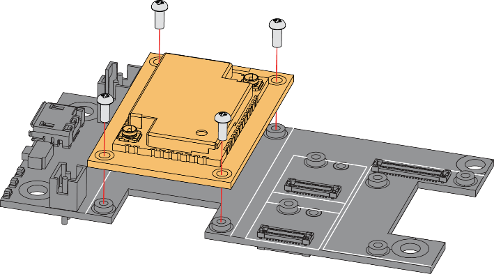 Figure 1: RAK4631-R mounting sketch
Disassembling
The procedure in disassembling any type of WisBlock module is the same.
- First, remove the screws.
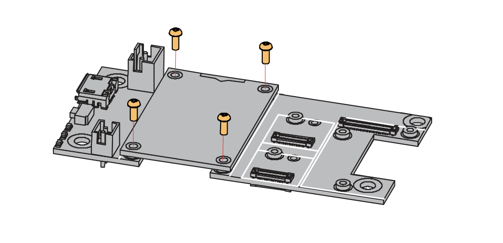 Figure 1: Removing screws from the WisBlock module
- Once the screws are removed, check the silkscreen of the module to find the correct location where force can be applied.
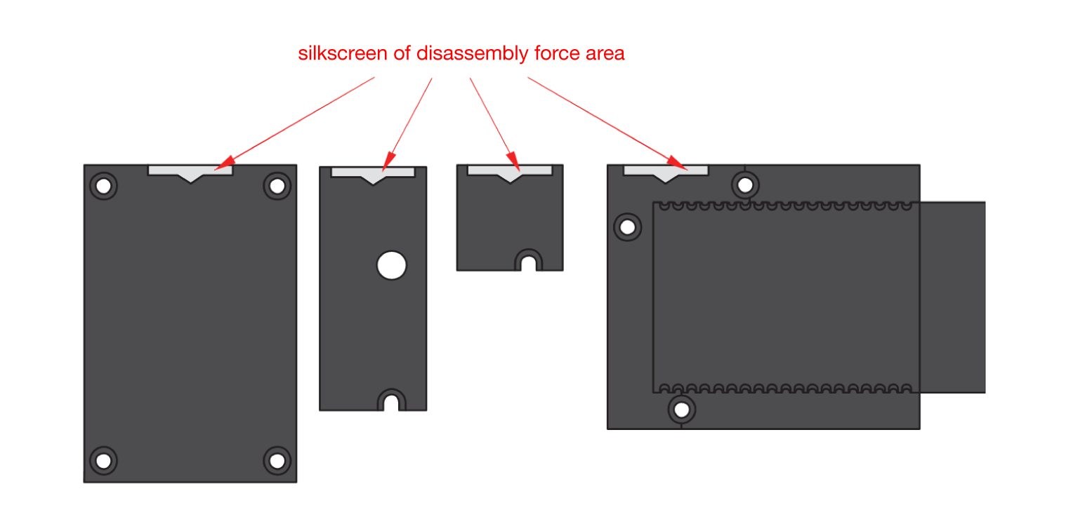 Figure 1: Detaching silkscreen on the WisBlock module
- Apply force to the module at the position of the connector, as shown in Figure 7, to detach the module from the baseboard.
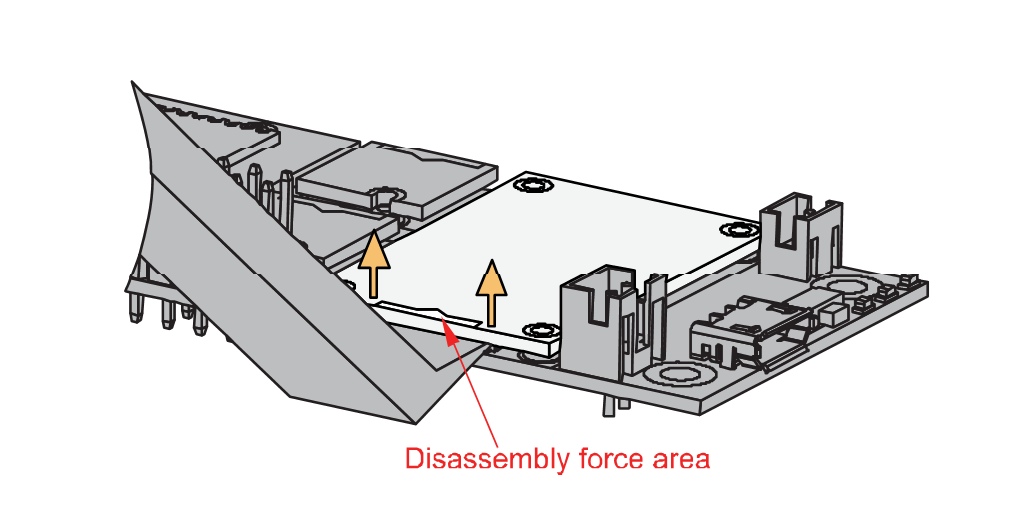 Figure 1: Applying even forces on the proper location of a WisBlock module
LoRa and BLE Antenna
Another important part component of RAK4631-R is the antennas.
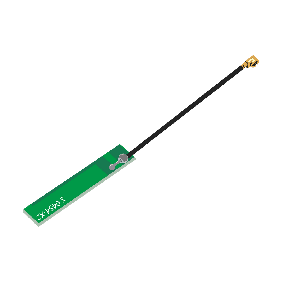 Figure 1: LoRa antenna
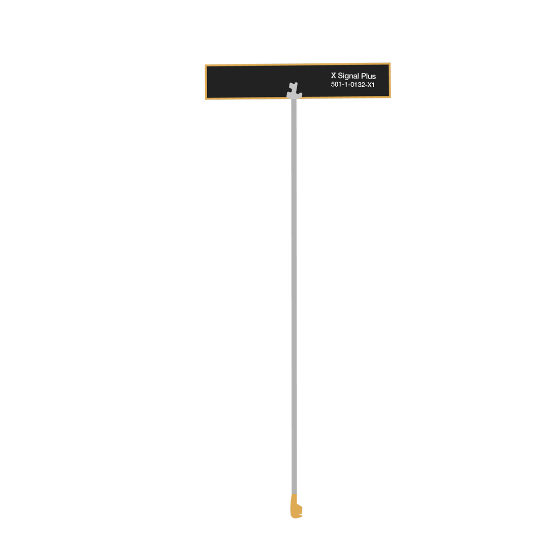 Figure 1: BLE antenna
You need to ensure that these are properly connected to have a good LoRa and BLE signal. Also, note that you can damage the RF section of the chip if you power the module without an antenna connected to the IPEX connector.
RAK4631-R has a label on its sticker on where to connect the antennas, as shown in Figure 10.
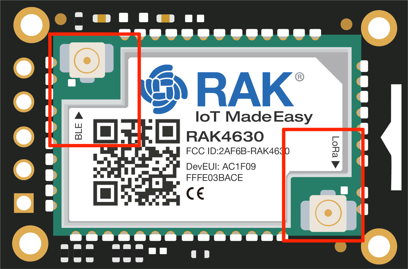 Figure 1: RAK4631-R antenna label
Detailed information about the RAK4631-R BLE and LoRa antenna can be found on the antenna datasheet.
When using the LoRa or Bluetooth Low Energy transceivers, make sure that an antenna is always connected. Using these transceivers without an antenna can damage the system. Make sure to fix the module with the screws to ensure a proper function.
Battery and Solar Connection
RAK4631-R can be powered via the USB cable or Li-Ion/LiPo battery via the dedicated connectors, as shown in Figure 11. The matching connector for the battery wires is a JST PHR-2 2 mm pitch female.
This illustration uses RAK5005-O as WisBlock Base. There are other WisBlock Base boards available, and you need to check the datasheet of the specific WisBlock Base board for the right polarity and other parameters.
- Batteries can cause harm if not handled properly.
- Only 3.7-4.2 V Rechargeable LiPo batteries are supported. It is highly recommended not to use other types of batteries with the system unless you know what you are doing.
- If a non-rechargeable battery is used, it has to be unplugged first before connecting the USB cable to the USB port of the board to configure the device. Not doing so might damage the battery or cause a fire.
- Only 5 V solar panels are supported. Do not use 12 V solar panels. It will destroy the charging unit and eventually other electronic parts.
- Make sure the battery wires match the polarity on the RAK5005-O board. Not all batteries have the same wiring.
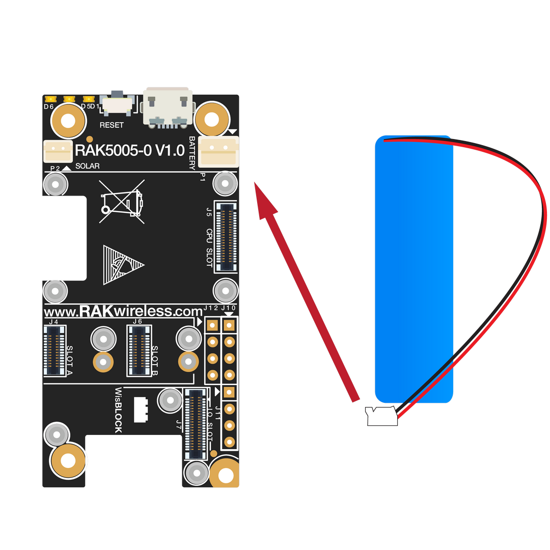 Figure 1: WisBlock Base connection
The battery can be recharged, as well, via a small solar panel, as shown in Figure 12. The matching connector for the solar panel wires is an JST ZHR-2 1.5 mm pitch female.
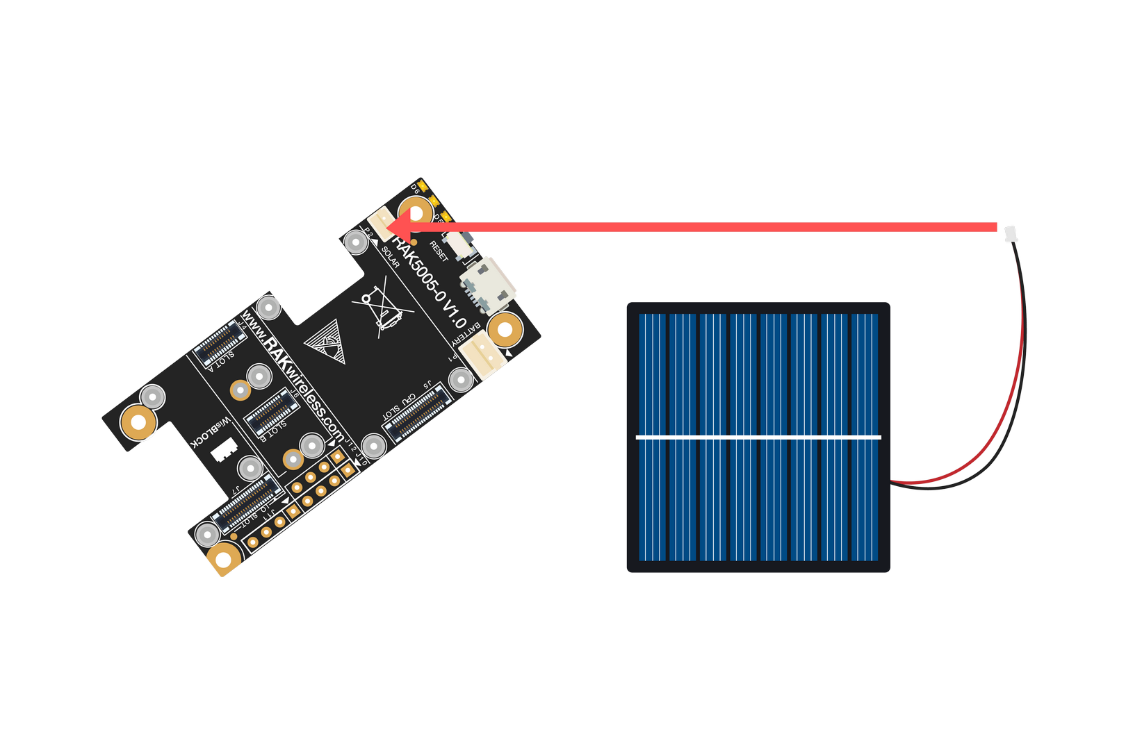 Figure 1: Solar panel connection
Specification of the battery and solar panel can be found on the datasheet of the WisBlock Base.
Software Initial Guide
The firmware of RAK4631-R allows you to develop custom firmware on top of its built-in AT Commands setting. To develop your firmware using Arduino IDE, you need first to add RAKwireless RUI nRF Boards in the Arduino board manager, which will be discussed in this guide. You can then use RUI3 APIs for your intended application. For the AT commands, you can send it either via a USB connection, UART1, or wirelessly via BLE connection.
This section covers:
- Arduino IDE with RAK4631-R
- Visual Studio IDE with RAK4631-R
- AT Command Demo via BLE
- More guides can be found on Demo and Examples page
RAK4631-R Board Support Package in Arduino IDE
If you don't have an Arduino IDE yet, you can download it on the Arduino official website and follow the installation procedure in the miscellaneous section of this document.
For Windows 10 users: If your Arduino IDE was installed from the Microsoft App Store, you need to reinstall your Arduino IDE by downloading it from the Arduino official website. The Arduino app from the Microsoft App Store has problems using third-party Board Support Packages.
Once Arduino IDE has been installed successfully, and you've understood the main parts of Arduino IDE, you can do some configuration changes on Arduino IDE so that it can be adapted to RAKWireless WisBlock.
- Open Arduino IDE and go to File > Preferences.
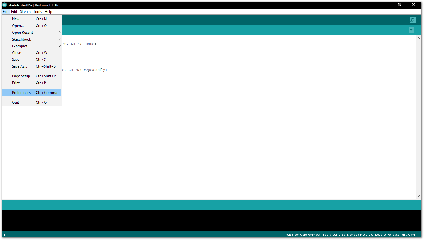 Figure 1: Arduino preferences
- To add the RAK4631-R WisBlock Core to your Arduino Boards list, you need to edit the Additional Board Manager URLs. Click the icon, as shown in Figure 14.
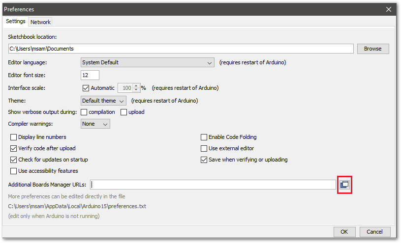 Figure 1: Modifying additional Board Manager URLs
- Copy the URL
https://raw.githubusercontent.com/RAKWireless/RAKwireless-Arduino-BSP-Index/main/package_rakwireless_com_rui_index.jsonand paste it on the field, as shown in Figure 15. If there are other URLs already there, just add them on the next line. After adding the URL, click OK.
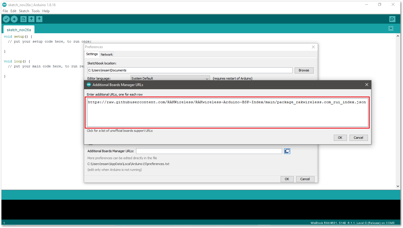 Figure 1: Add additional Board Manager URLs
-
Restart the Arduino IDE.
-
Open the Boards Manager from Tools Menu.
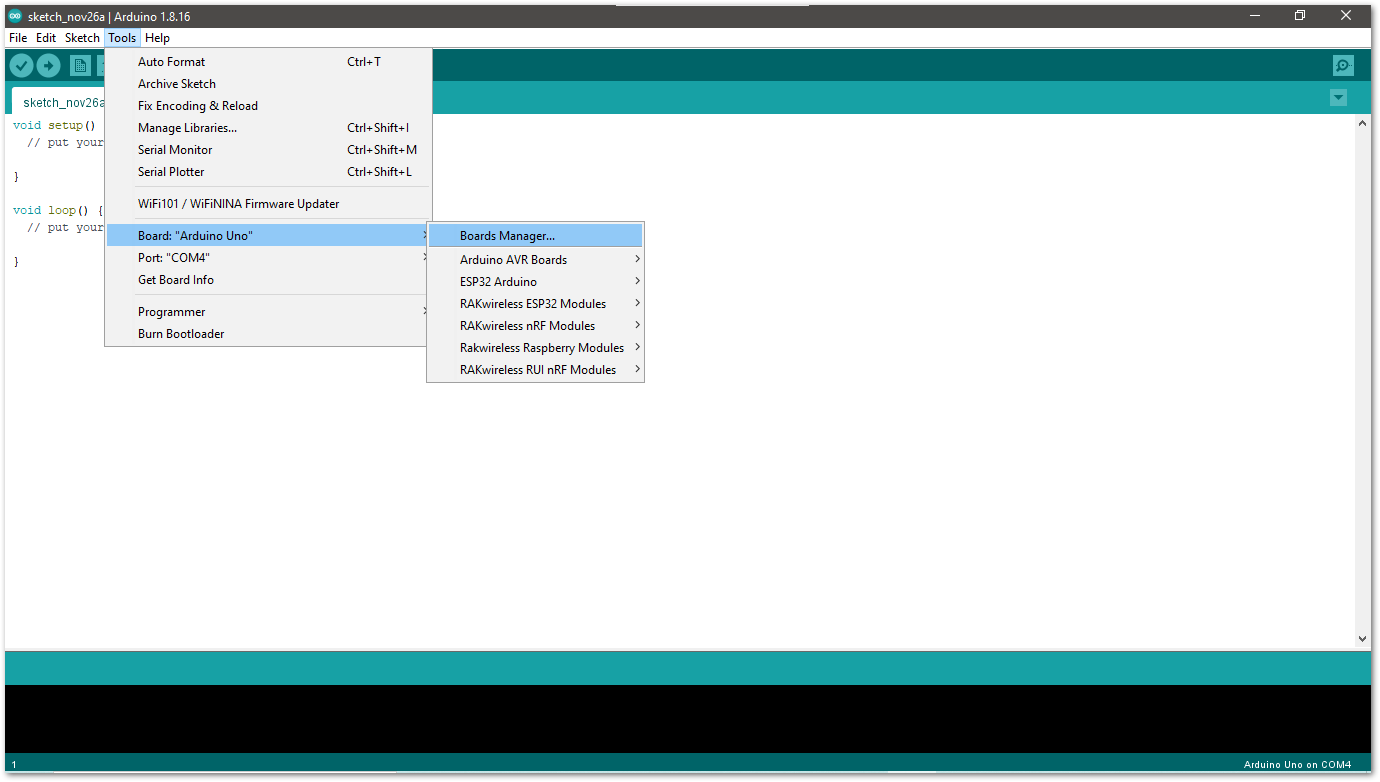 Figure 1: Opening Arduino Boards Manager
- Write
RAKin the search bar, as shown in Figure 17. This will show the available RAKwireless WisBlock Core boards that you can add to your Arduino Board list. Select and install the RAKwireless RUI nRF Boards
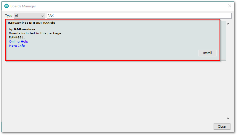 Figure 1: Installing RAKwireless RUI nRF boards
- Once the BSP is installed, select Tools > Boards Manager > RAKWireless RUI nRF Modules > WisBlock Core RAK4631 Board.
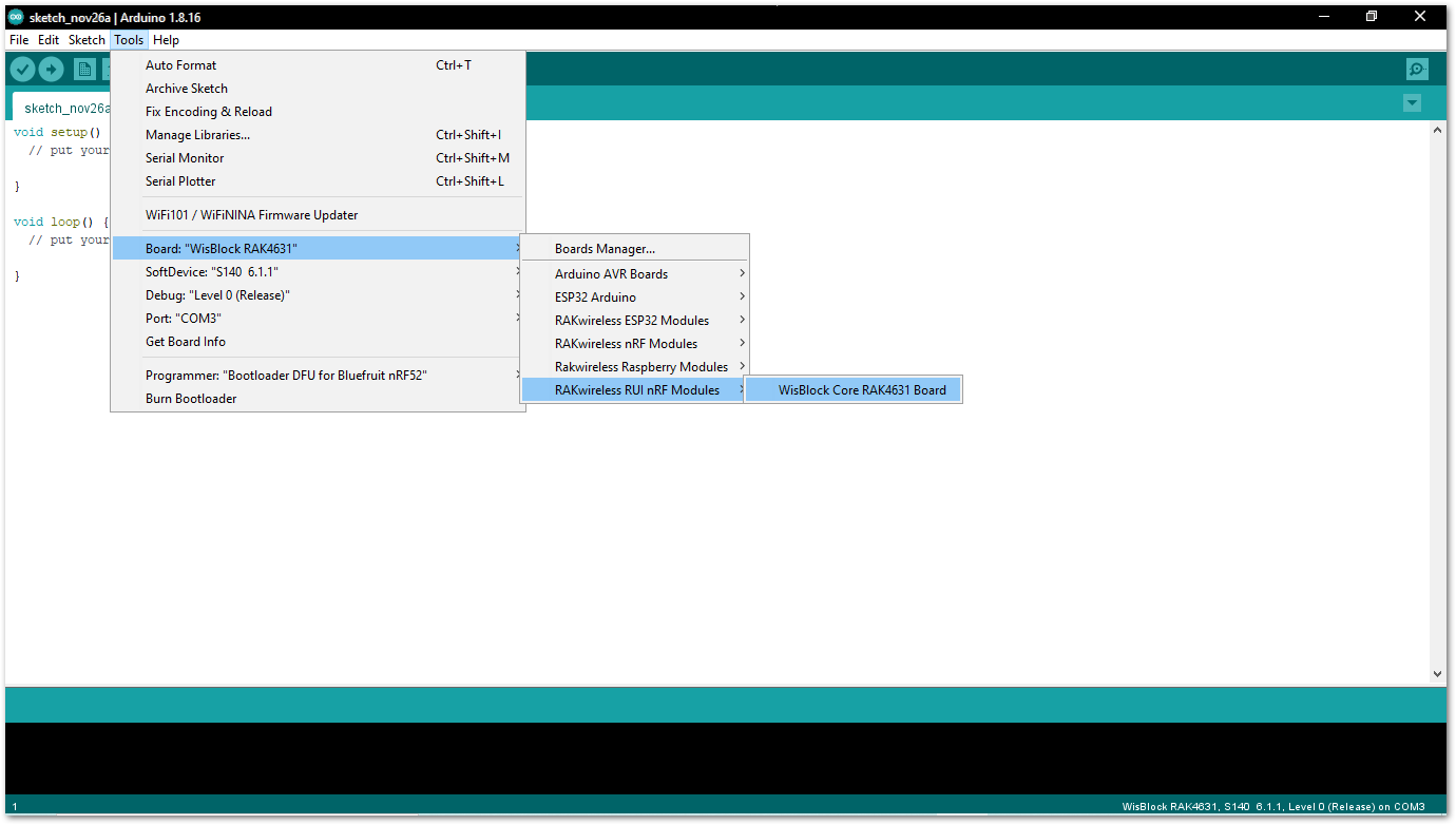 Figure 1: Selecting RAKwireless WisBlock Modules
Programming RAK4631-R via Visual Studio IDE
Visual Studio IDE Download and Installation
If you don't have Visual Studio IDE yet, download the installer on Visual Studio IDE Community 2019.
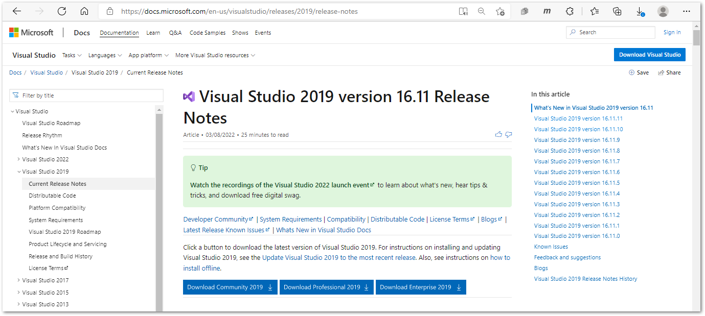 Figure 1: Visual Studio Community 2019 Release Notes
Windows Setup
Install the Visual Studio Community 2019, which you just downloaded, on your Windows PC.
- Click the Continue button.
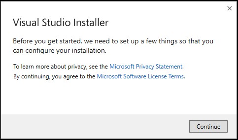 Figure 1: Visual Studio Community License
- On the next installer window, select the Desktop development with C++ tab and then click on the Install button.
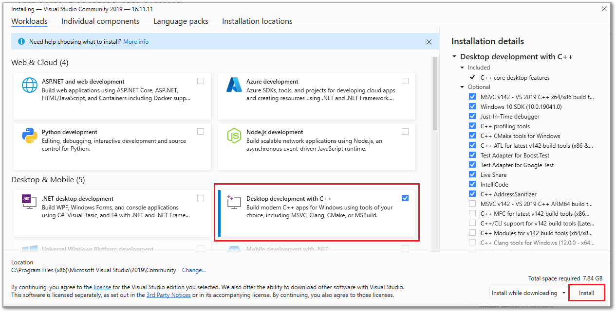 Figure 1: Visual Studio Community 2019 desktop development with C++
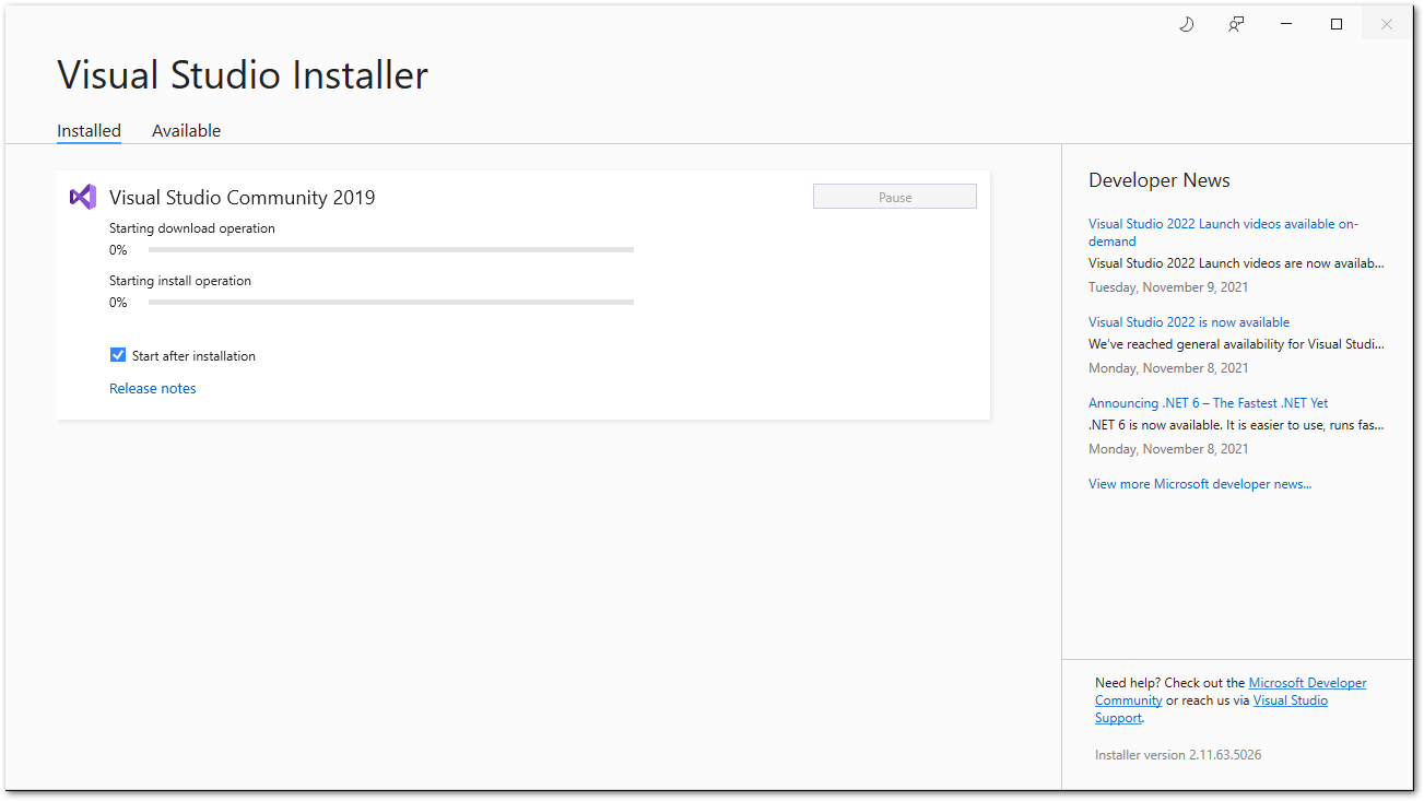 Figure 1: Visual Studio Community 2019 installer
- A reboot is required after the successful installation. Restart your computer first before you start using Visual Studio.
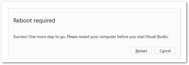 Figure 1: Visual Studio Community 2019 successful installation
-
After restarting your computer, download the Arduino IDE for Visual Studio 2019.
- Alternative link: Arduino IDE for Visual Studio 2019
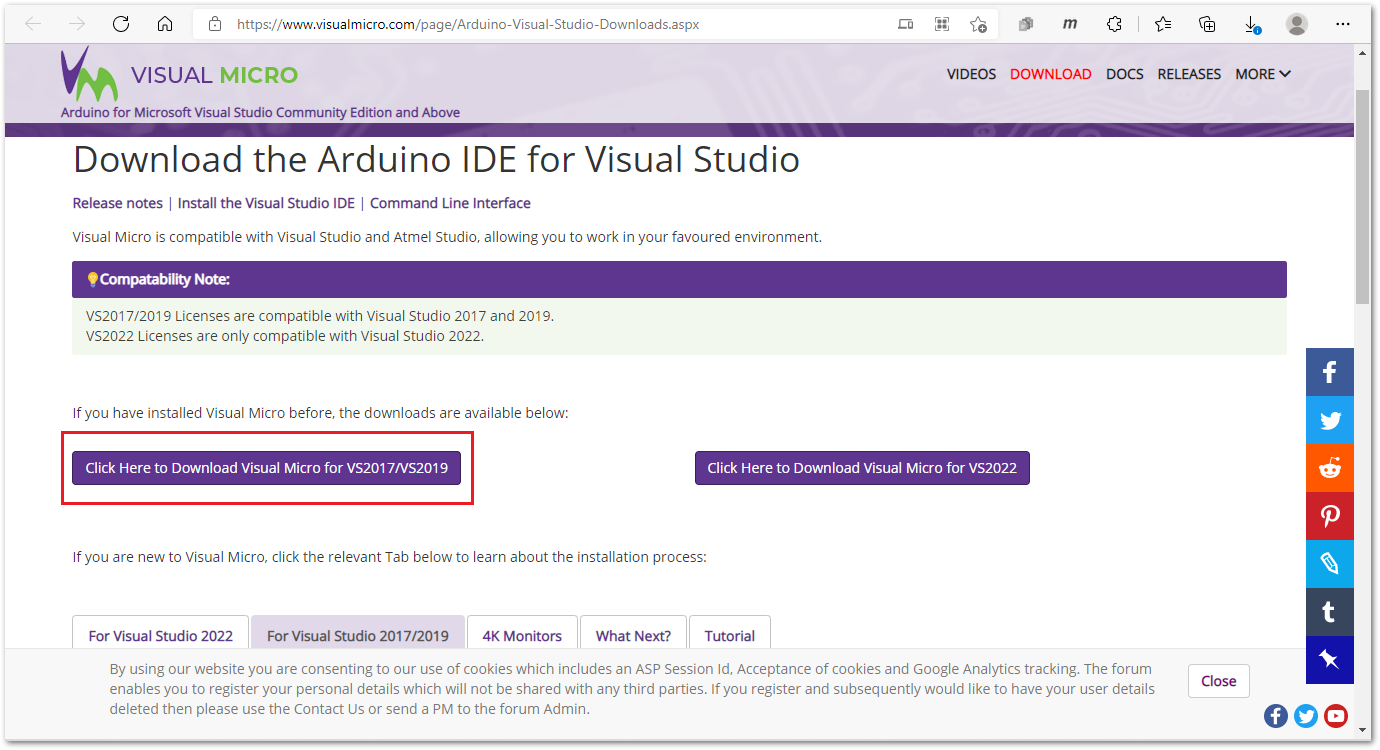 Figure 1: Arduino IDE for Visual Studio
- Click on the Install button to install the Arduino IDE VSIX extension.
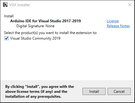 Figure 1: Arduino IDE VSIX extension install
- Arduino IDE VSIX installation completed.
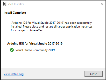 Figure 1: Arduino IDE VSIX extension successfully installed
Configuring Visual Studio Community 2019
- Open Visual Studio 2019 then click on the Continue without code.
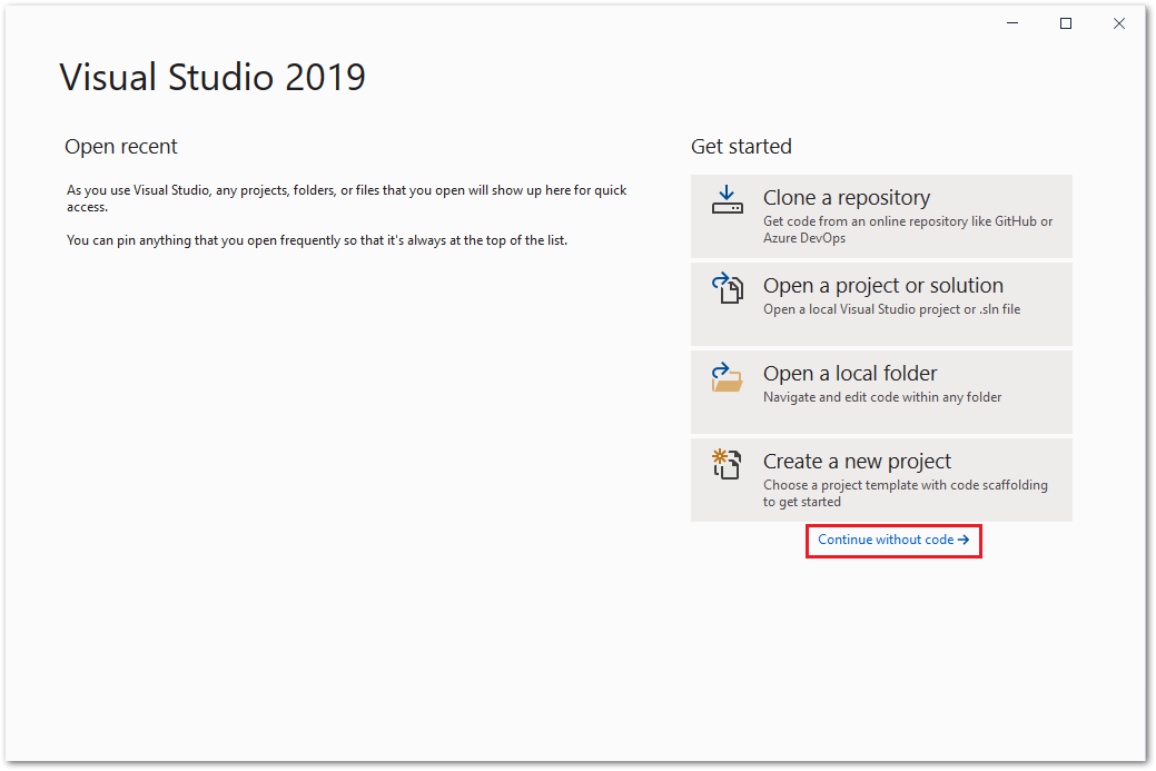 Figure 1: Open Visual Studio Community 2019 App
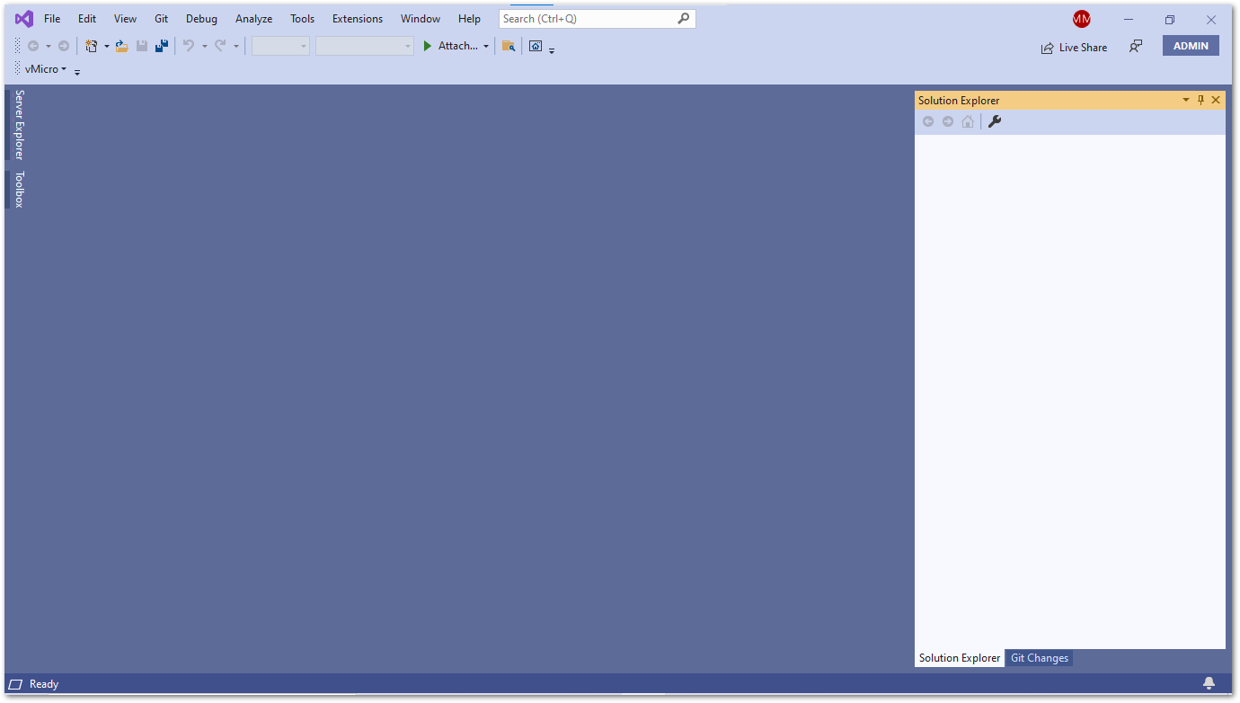 Figure 1: Visual Studio Community 2019
- In the Menu tab, click Extensions and select vMicr then Visual Micro Explorer.
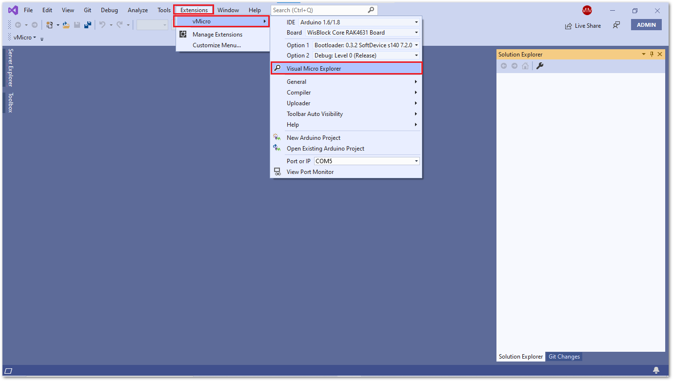 Figure 1: Visual Studio Community 2019 Micro Explorer configuration
- A Micro Explorer window appears. Under the IDE tab, select IDE Arduino 1.6/1.8 then click on the IDE Locations tab.
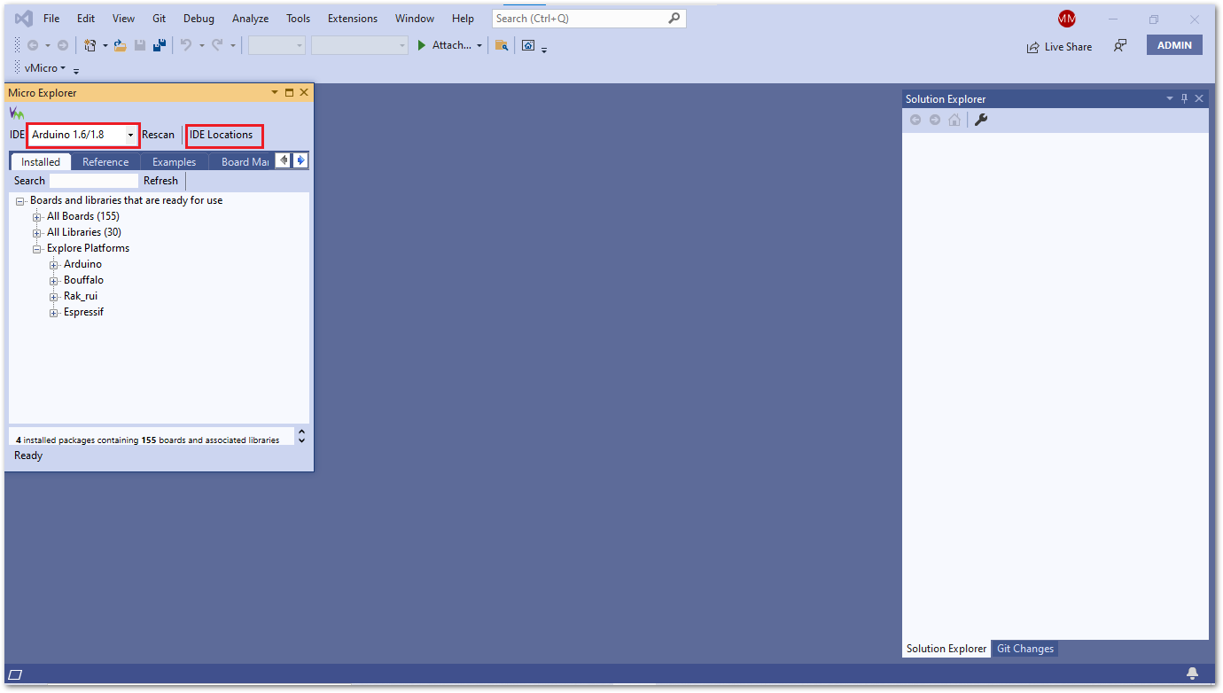 Figure 1: Visual Studio Community 2019 Micro Explorer configuration
- After that, execute the following to configure the IDE Locations:
- On Use installed IDE field, select Arduino 1.6/1.8.
- Check if the Arduino IDE is already installed on folder
C:\Program Files (x86)\Arduino. - Copy the RUI URL:
https://raw.githubusercontent.com/RAKWireless/RAKwireless-Arduino-BSP-Index/main/package_rakwireless_com_rui_index.jsonand paste it on Optional addition boards manager urls.
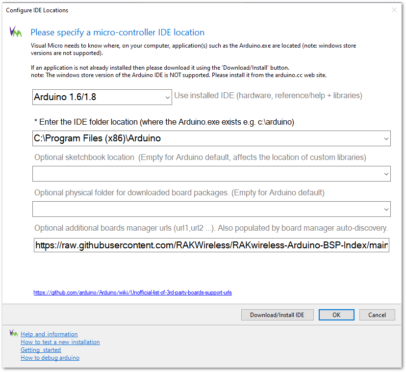 Figure 1: Visual Studio Community 2019 IDE Locations configuration
- Install RAKwireless RUI nRF Boards.
- Restart the Visual Studio IDE.
- Open the Visual Micro Explorer on the Extensions -> vMicro -> Visual Micro Explorer.
- Click on the Board Manager tab and check RAKwireless RUI nRF Boards. This will show the available versions of RAKwireless RUI nRF boards.
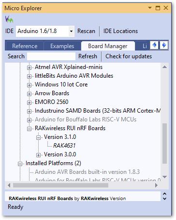 Figure 1: Visual Micro Explorer Board Manager RAKwireless
- Select the latest available version of RAKwireless RUI nRF board and then click OK to install.
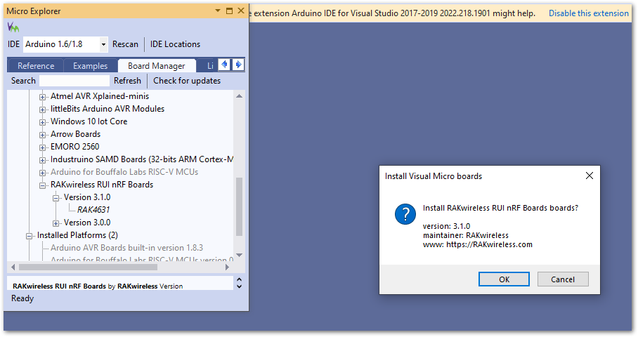 Figure 1: Board Manager installation
You can also install RAKwireless RUI nRF Boards using the RAK4631-R Board Support Package. The Visual Studio IDE 2019 imports Arduino IDE settings.
Compile an Example With RAK4631-R
- Launch Visual Studio IDE and open Visual Micro Explorer on Extensions -> vMicro -> Visual Micro Explorer.
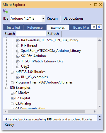 Figure 1: Micro Explorer examples
- Click on the Examples tab and then search for RAK4631 on the RUI_V3_examples folder.
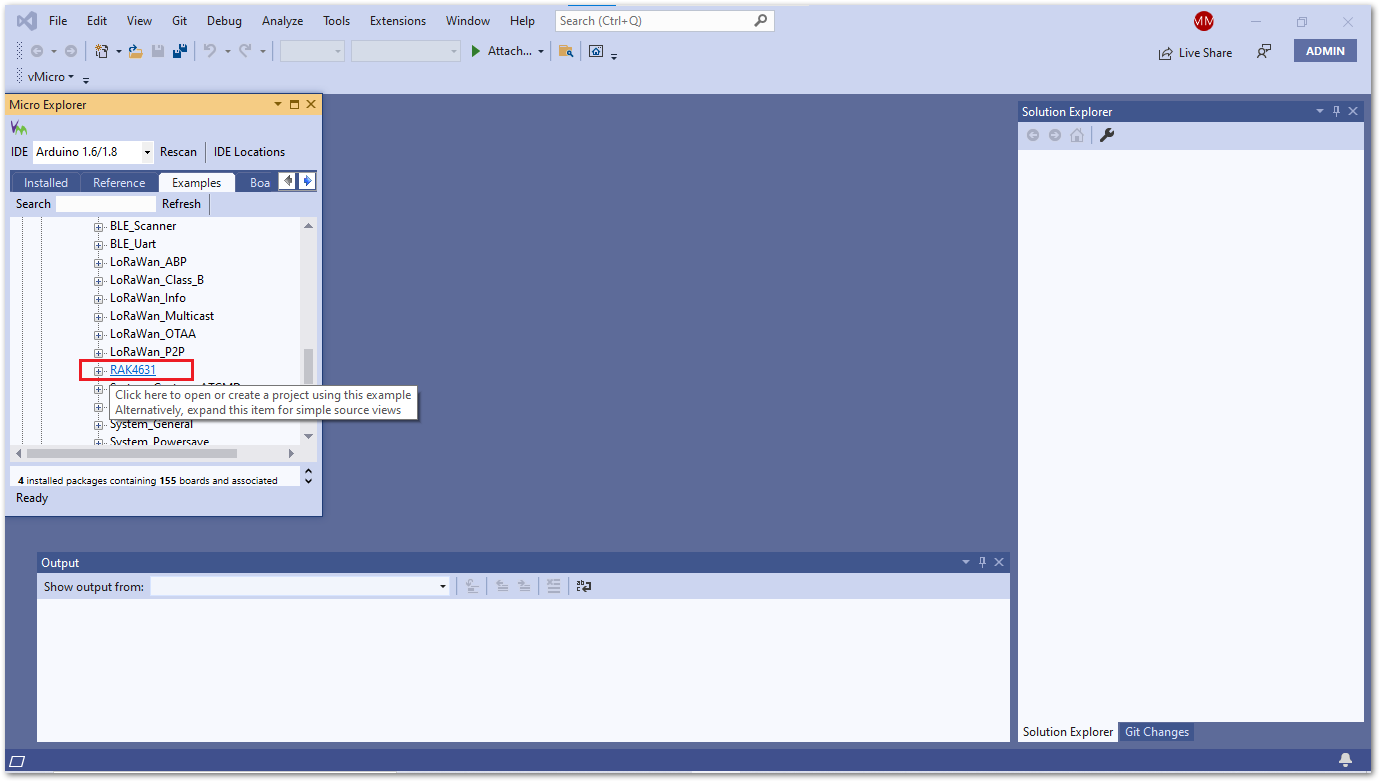 Figure 1: Micro Explorer RAK4631 examples
- In the Visual Micro - Help and Examples window, click on the Open Copy button.
- Now, close the Micro Explorer window and open the Arduino sketch on the Solution Explorer window:
- Click on the x icon to close
Micro Explorer. - Click on the triangle icon to open
Solution Explorer.
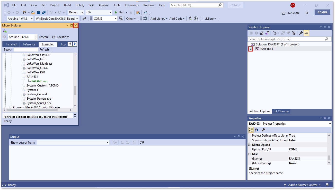 Figure 1: RAK4631 Solution Explorer
- In the Solution Explorer, under RAK4631, click the
RAK4631.inofile.
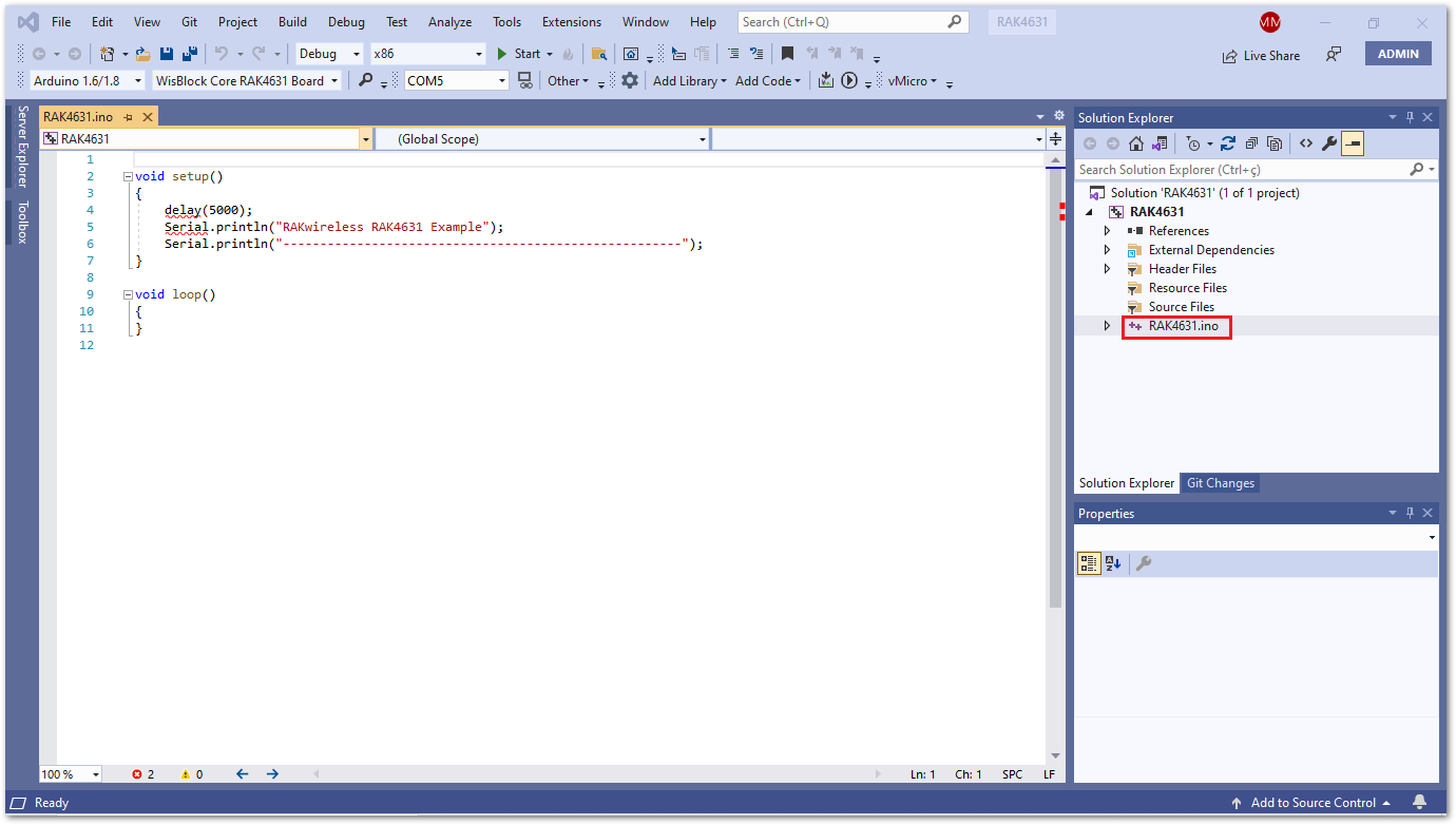 Figure 1: Opening the RAK4631.ino file
- Configure Solution, Platform, and Serial Port. Click the dropdown and choose the following:
- Solution Configuration field: Release
- Solution Platforms field: x86
- Serial Portfield: Choose the RAK4631-R COM port detected in the Windows Device Manager.
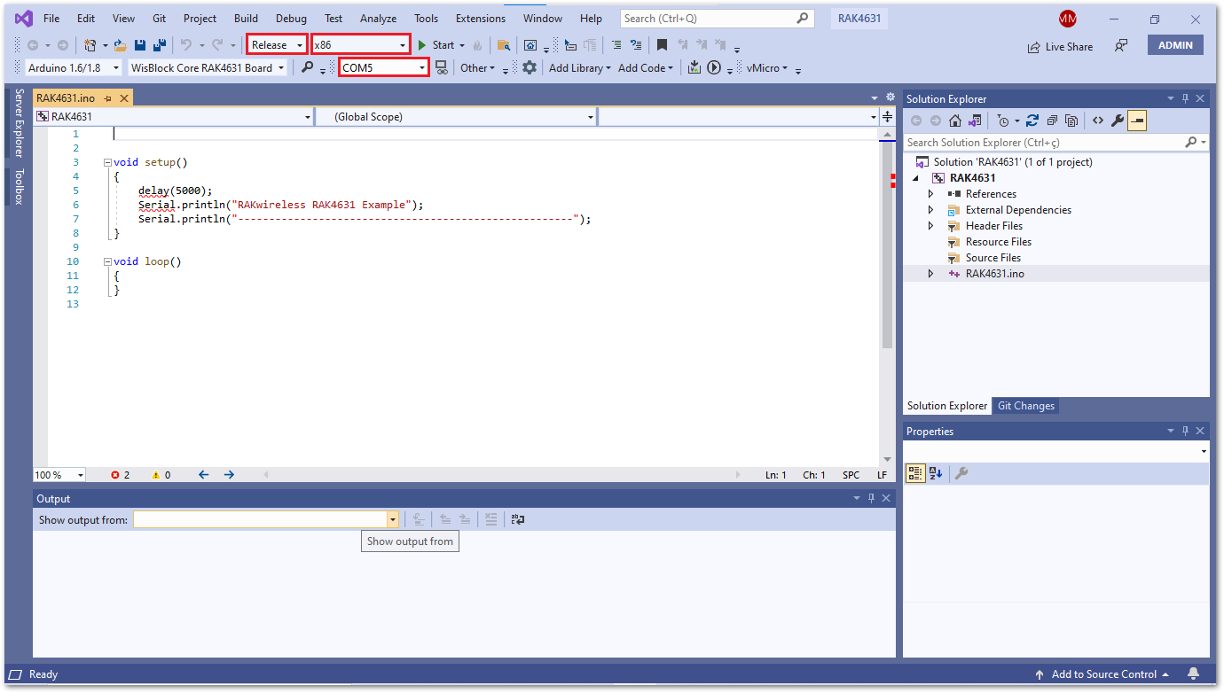 Figure 1: RAK4631.ino file
- Click on the Build and Upload icon to flash the project on RAK4631-R.
RAK4631-R should automatically go to BOOT mode when the firmware is uploaded via Arduino IDE.
If BOOT mode is not initiated, pull to ground the RESET pin twice (or double click the reset button if available) to force BOOT mode.
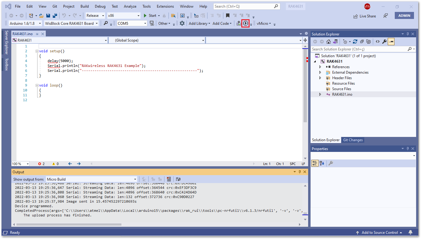 Figure 1: Build and upload the RAK4631-R project
After a successful upload, you can now use your preferred console UART tool to connect with the RAK4631-R COM port. If the connection is successful, then you will see the output messages.
- Type the following commands to check the current firmware version:
ATE
AT+VER=?
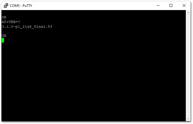 Figure 1: UART console output
AT Command Over BLE
This section shows how to use AT Commands over BLE using a Serial Bluetooth Terminal.
All available commands can be found in the AT Command Manual of RAK4631-R.
- Download and install the Serial Bluetooth Terminal to connect the device.
- Make sure the Bluetooth on your mobile is turned on.
- Select Category then Devices.
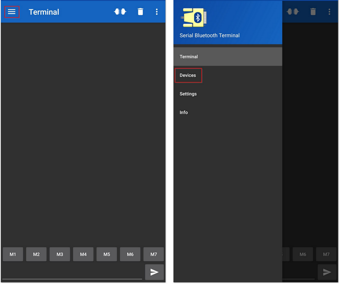 Figure 1: Available Serial Bluetooth Terminal
- Select the Bluetooth LE icon and click the SCAN icon to scan the device.
- Look for a BLE Device named "RAK.XXXXXX" in the scanner list of the app and connect to this device.
By default, the BLE signal of the RAK4631-R turns off automatically if no connection is established after 30 seconds. Connect to the BLE signal of the RAK4631-R immediately after pressing the reset button.
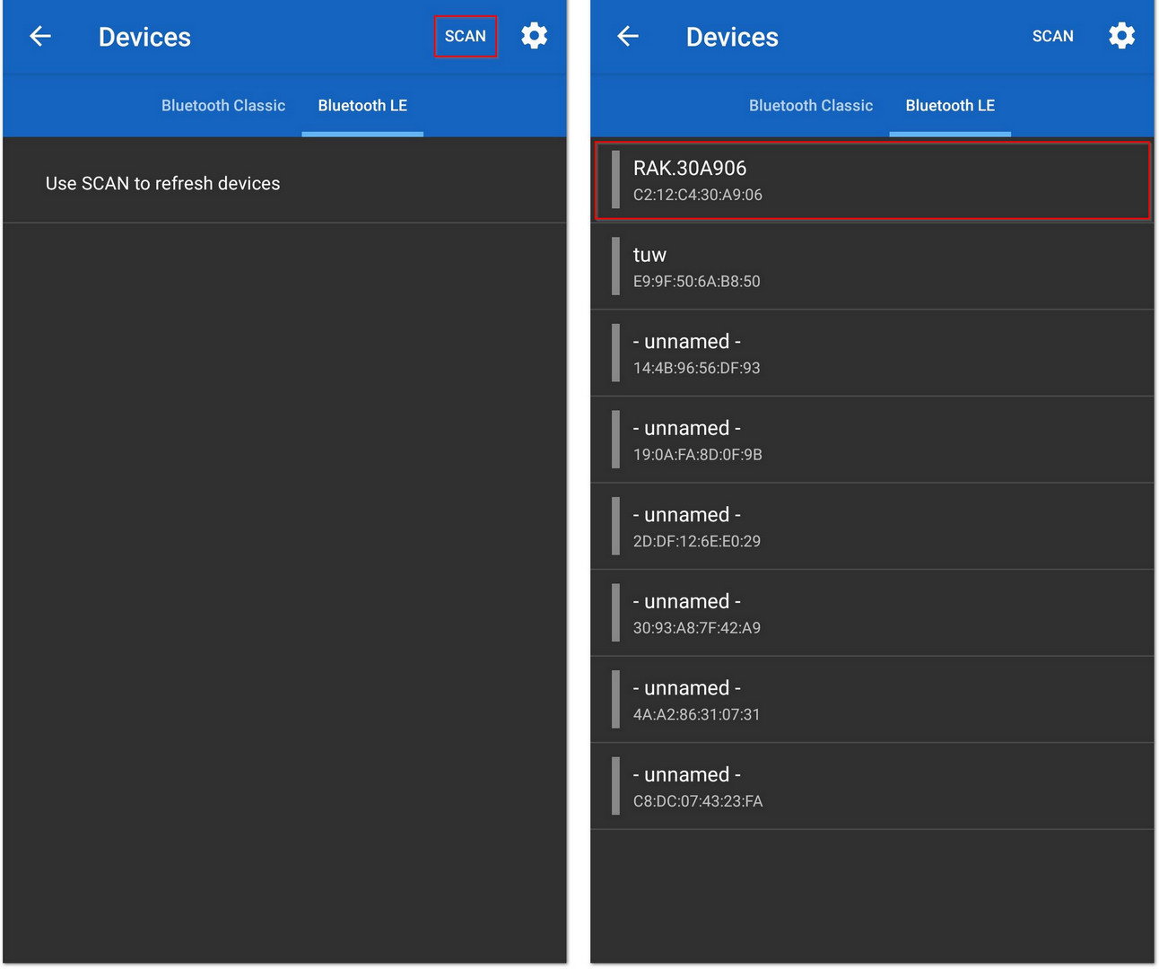 Figure 1: Scanning devices
- Make sure the connection is successful with "RAK.XXXXXX".
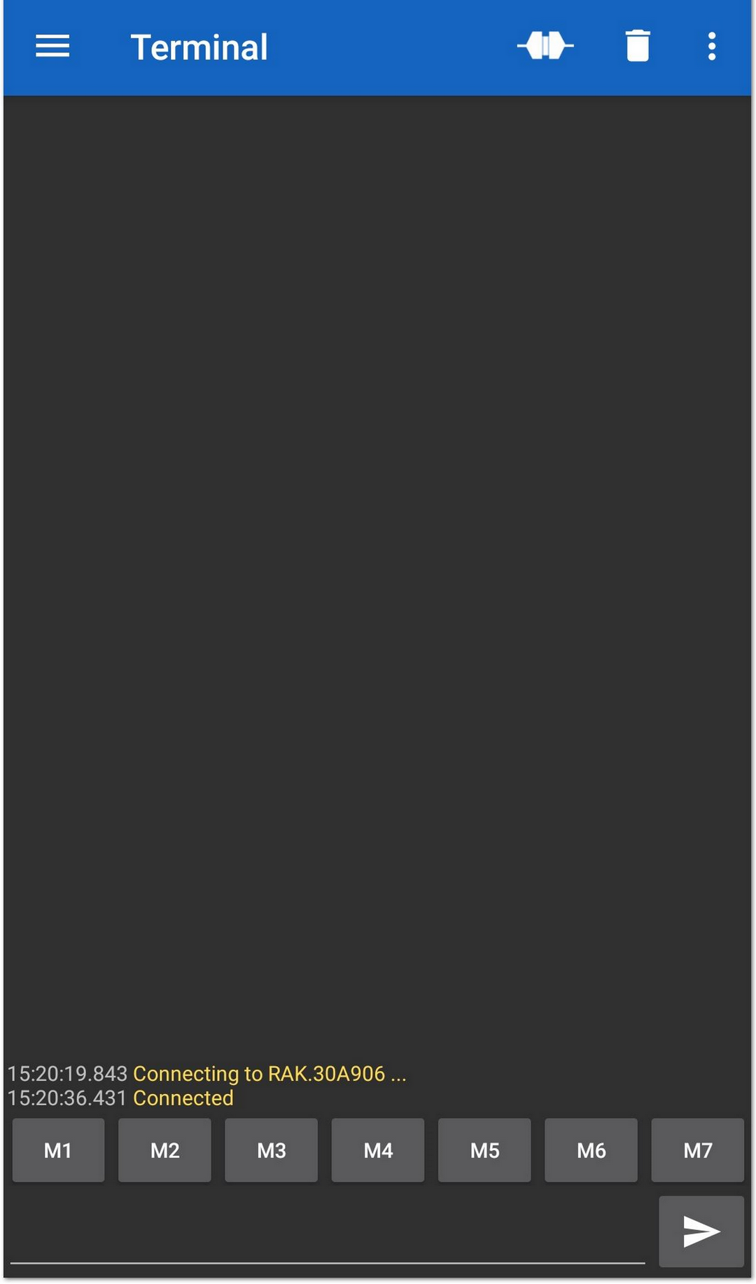 Figure 1: Connect with the device
- Send an AT Command and check remote console is received or not.
at+ver=?
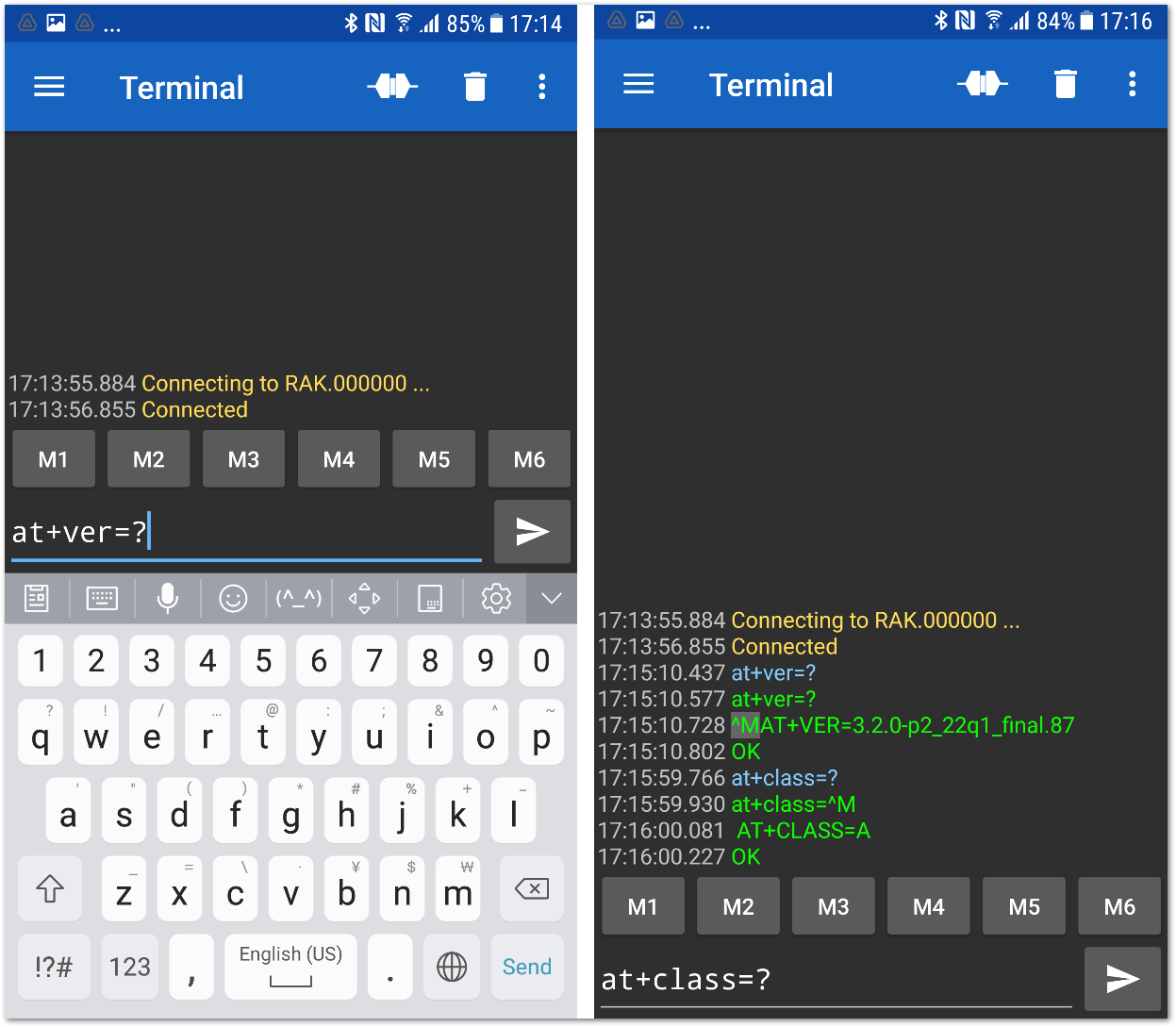 Figure 1: RAK4631-R default Bluetooth ID after resetting
- The remote device will receive the same AT Commands.
at+ver=?
AT+VER=3.2.0-p2_22q1_final.87

OK

at+class=?
AT+CLASS=A

OK
Miscellaneous
Arduino Installation
Go to Arduino official website and download the Arduino IDE. You can see the multiple versions available for Windows, Linux, and Mac OS X. Choose the correct version of Arduino IDE and download it.
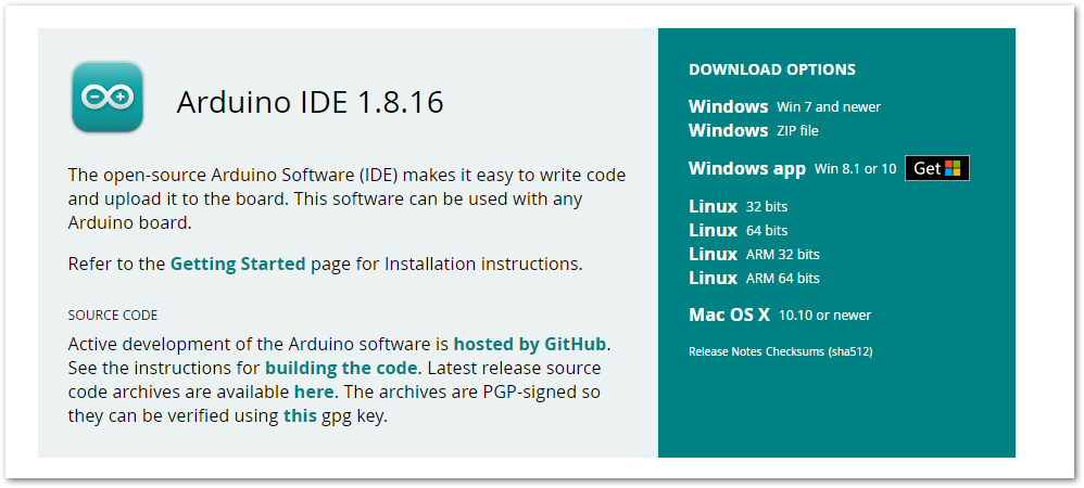 Figure 1: Arduino IDE latest version
For Windows
For Windows 10 users: Do NOT install the Arduino IDE from the Microsoft App store. Install the original Arduino IDE from the Arduino official website. The Arduino app from the Microsoft App Store has problems using third-party Board Support Packages.
- Install the Arduino IDE, which you just downloaded, on your Windows PC.
- Click I Agree then Next to proceed.
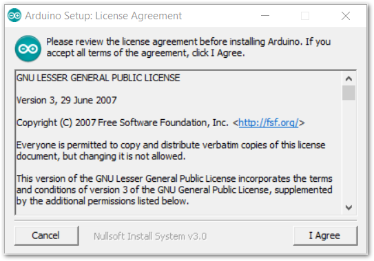 Figure 1: Arduino Setup License Agreement
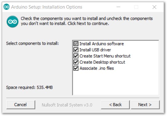 Figure 1: Arduino Setup Installation Options
- Click Install.
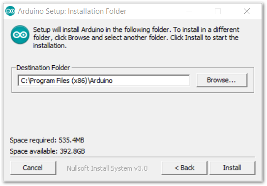 Figure 1: Installing Arduino IDE
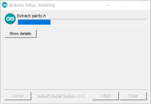 Figure 1: Ongoing Installation
After 100% progress, the Arduino IDE has been installed successfully.
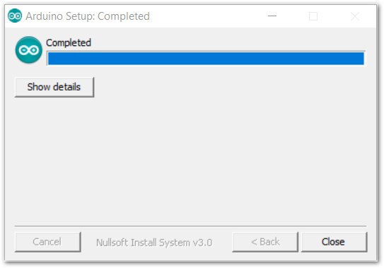 Figure 1: Successful Installation
For Linux
First, you need the check the compatibility with your system and choose between the 32-bit, 64-bit, and ARM versions of the Arduino IDE for Linux.
Installing via a tarball
- After downloading the correct Arduino version, open a terminal, then run
lsto check the installation file on the download folder.
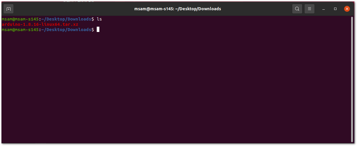 Figure 1: Check the download folder
- A tarball is a type of compressed folder, like a
.zipfile, commonly used to distribute software in Linux. To extract the files from the tarball, change the directory to where the downloaded tarball is, then run:
tar xvf arduino-version.xz
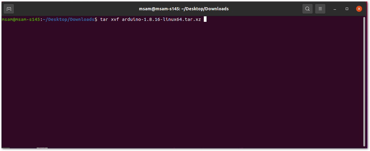 Figure 1: Tarball extract command
- When the tar command is finished, run
lsagain. A folder named arduino-version will be created.
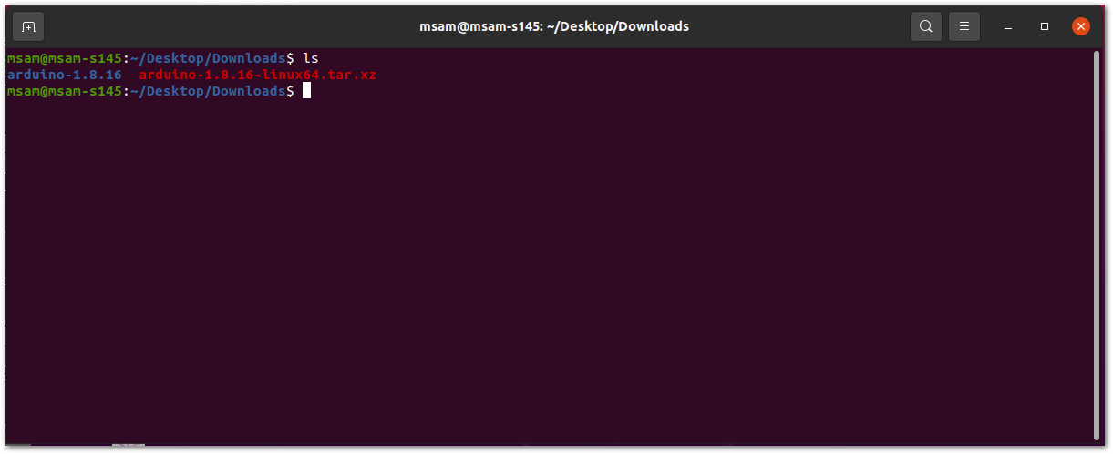 Figure 1: Arduino install folder created
- Change the current directory and go to the newly created folder directory. There will be a file named
install.shin the folder. Executesudo ./install.shto install the Arduino IDE.
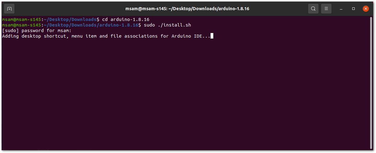 Figure 1: Arduino install script running
The sudo command temporarily elevates privileges allowing the installer to complete sensitive tasks without logging in as the root user.
For Mac OS X
In Mac OS X, the same as Linux, there is no installation process. It is just a process of decompression, then you can open Arduino IDE successfully.
Arduino IDE Parts Guide
Figure 57 shows the five (5) parts of Arduino IDE.
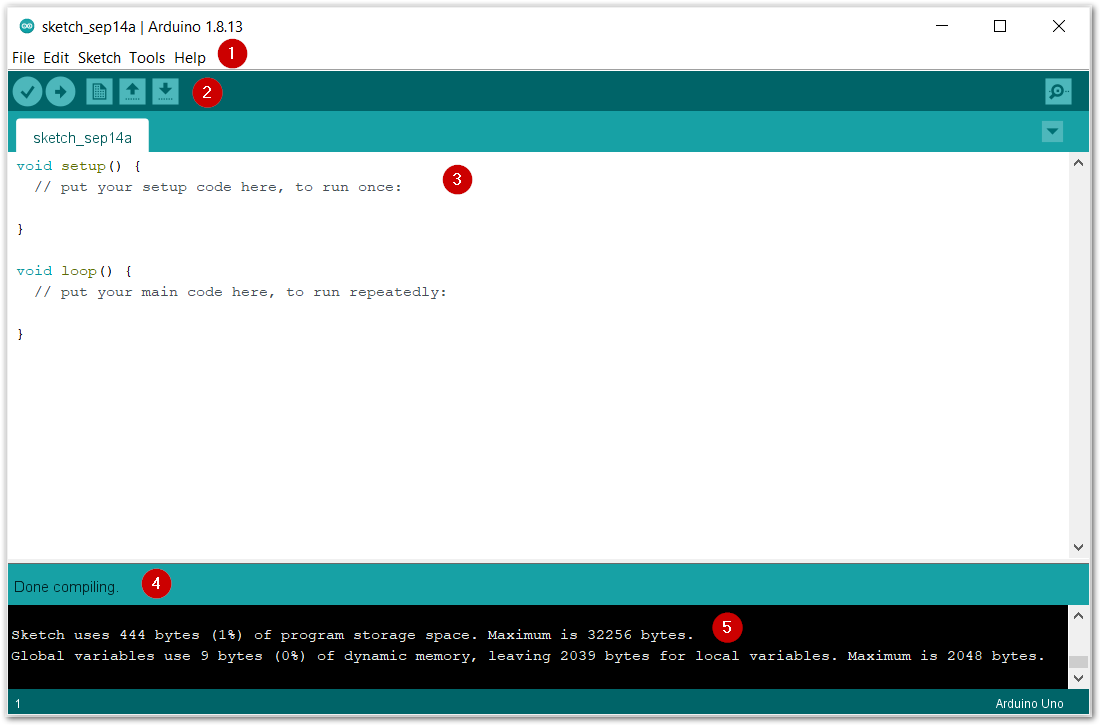 Figure 1: Arduino IDE
- IDE Option Menu
You can configure some general parameters such as the serial port, the board information, the libraries, the edit parameters, and so on.
- Operating Buttons
The operating buttons have five operations:
- Verify/Compile the source code.
- Upload the compiled code into WisBlock.
- Open a New Arduino IDE window or existing application.
- Save the current application.
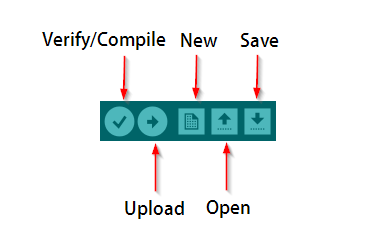 Figure 1: Operating Buttons
- Code Area
You can edit the source code, which will be compiled and uploaded into WisBlock later in this area.
-
State Area
-
Output Message Area You can see the output message in this area, whether it's failure or success information.
