RAK7268V2/RAK7268CV2 Installation & Setup Guide
This manual provides brief instructions for installing and deploying the gateway.
Prerequisites
Package Inclusions
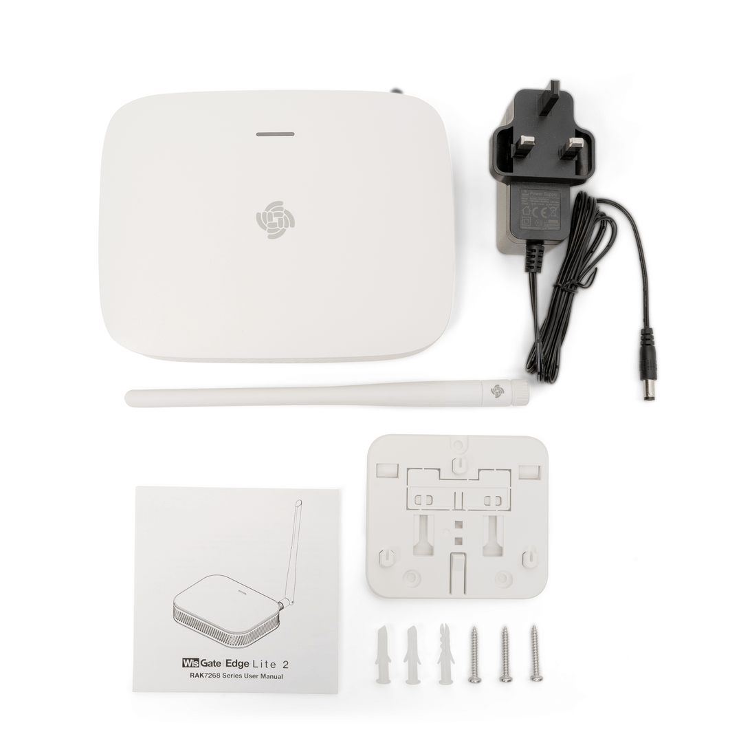 Figure 1: RAK7268V2/RAK7268CV2 package contents
- 1 × Gateway
- 1 × LoRa Antenna
- 1 × Power Supply Adapter
- 1 × Mounting Bracket with Installation Accessories
- 1 × User Manual
The contents shown in the image are for reference only and correspond to the general version of the gateway. The actual items included may vary depending on the bundle you purchased. For example, if you purchased a version with external LTE antennas, the package will include two LTE antennas.
Additional Hardware Required
- Ethernet Cable (RJ-45 Port) for Ethernet connection
- A Windows/MacOS/Linux Computer – For configuration via Web UI
- NanoSIM Card (for LTE version) – Size: 12 x 9 x 0.67 mm
Installation
Insert SIM Card (For cellular models only — RAK7268CV2)
The SIM card slot of the cellular versions is not hot-swappable. Make sure the gateway is switched off before inserting or ejecting the SIM card.
- On the back of the gateway, locate the NanoSIM card slot.
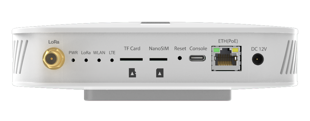 Figure 1: NanoSIM card slot
- Insert the NanoSIM card into the slot, ensuring it is securely seated.
Mount the Bracket
The gateway can be mounted in multiple ways: wall-mounting, ceiling-mounting, or using a rail. Choose the appropriate mounting style based on your environment and needs.
Wall Mounting
- Use a 5-mm drill bit to drill three holes on the wall where you want to mount the gateway. It’s recommended to mark the hole positions before drilling to ensure accurate placement.
- Insert expansion plugs into the drilled holes.
- Secure the mounting bracket to the wall using screws through the bracket holes.
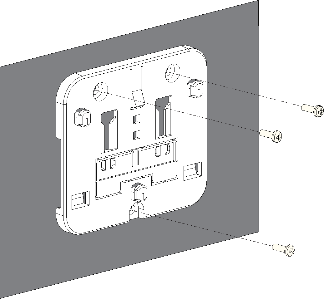 Figure 1: Wall-mounted bracket installation
Ceiling Mounting
For ceiling mounting, ensure the ceiling is strong enough to support the gateway. Mark the hole positions before drilling.
- Choose self-tapping screws or expansion tubes and self-tapping screws to install the bracket according to the actual material of the ceiling.
- (Optional) Refer to this step when installing the bracket using expansion tubes and self-tapping screws. Otherwise, skip it.
- Use a 5-millimeter drill bit to drill three holes in the ceiling.
- Insert the expansion tubes into the holes drilled in the ceiling.
- Secure the bracket to the ceiling using self-tapping screws through the holes in the bracket.
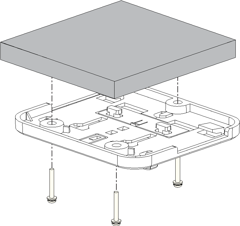 Figure 1: Ceiling-mounted bracket installation
T-Shaped Keel Mounting
You can use a T-shaped keel for mounting the bracket on a rail system. The following instructions apply to a T-shaped keel, but other types of rails can also be used.
The bracket supports rail widths of 14 mm, 16 mm and 24 mm.
- Remove the mounting clip from the bracket.
- Insert one side of the T-shaped keel into the two clips of the bracket.
- Insert the two T-shaped hooks on the mounting clip into the T-shaped rails of the bracket, slide the mounting clip to the other side of the T-shaped keel, and make sure the clip is in place.
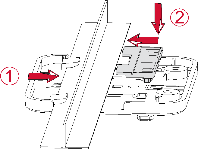 Figure 1: Bracket mounted on T-shaped keel structure
Install the Gateway
- Align the lower edge of the gateway's hanging hole with the bracket's locking plate.
- Move the gateway closer to the bracket so that the bracket's locking plate enters the gateway's hanging hole.
- Pull the gateway to ensure that the gateway is in place.
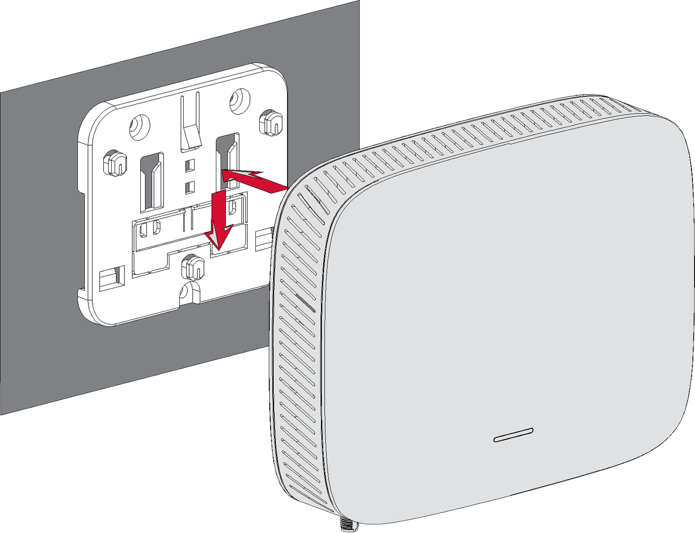 Figure 1: Fixed gateway
Attach the Antenna
- LoRa Antenna
Attach the LoRa antenna by screwing it onto the connector labeled LoRa on the gateway. - LTE Antennas (if applicable)
For gateway models with external LTE antenna support, screw the LTE antennas onto the RP-SMA connectors labeled MAIN and AUX.
Power On and Status Verification
Power the Gateway
Do not power the device if any antenna port (LoRa or LTE) has been left open to avoid potential damage to the RAK7268V2/RAK7268CV2 WisGate Edge Lite 2.
The RAK7268V2/RAK7268CV2 can be powered using one of the following options:
- Power Adapter (Recommended, included in the package)
- Connect the power adapter to the device.
- Plug the other end of the adapter into a power outlet.
- Power over Ethernet (PoE, Optional)
- Connect an Ethernet cable to the device's ETH(PoE) port.
- Ensure the PoE switch or injector (not included in the shipment) is properly connected and powered.
Startup Status Checklist
To verify if the gateway is operating normally after powering on, check the following:
| LED | Expected Status After Power-On | Description |
|---|---|---|
| PWR | ON (solid) | Power is connected; the gateway is powered on. |
| Breathing | Red (fast blinking) | When the gateway is first powered on and not yet connected to the internet, the LED will show red with a fast blink to indicate a network issue. Once the gateway successfully connects to the internet, the LED will switch to blue with a slow blink, indicating normal operation. |
| ETH (if Ethernet is connected) | ON / Flickering | Ethernet port is active; data transmission may be occurring. |
| WLAN | ON / Flickering | WiFi AP mode is active and functional. |
| LoRa | ON / Flickering | Indicates the LoRa transceiver is operational and handling packets. |
| LTE (RAK7268CV2 only) | Fast flickering or slow idle blinking | LTE module is either transmitting data or searching for a network. |
For more detailed LED behavior and additional indicators, refer to the RAK7268V2/RAK7268CV2 LED Indicators.