RAK2461 WisNode Bridge IO Lite DO Device Configuration Guide
This guide explains how to connect a DO (Digital Output) device to the Bridge IO, configure output control, and send commands via LoRaWAN®.
Prerequisite
Before configuring DO (Digital Output), prepare the following:
-
A DO (Digital Output) device.
-
Gateway in range
-
IO.Box (latest version recommended)
Connect DO Device to Bridge IO Device
This section demonstrates how to use the Bridge IO Digital Output interface and its internal power output to connect and control a bulb (supports 5 VDC input).
-
Connect the 5V_Out terminal of the Bridge IO to one terminal of the bulb.
-
Connect the other terminal of the bulb to the COM terminal of the selected DO channel.
-
Connect the NO terminal of the DO channel to the GND terminal of the Bridge IO.
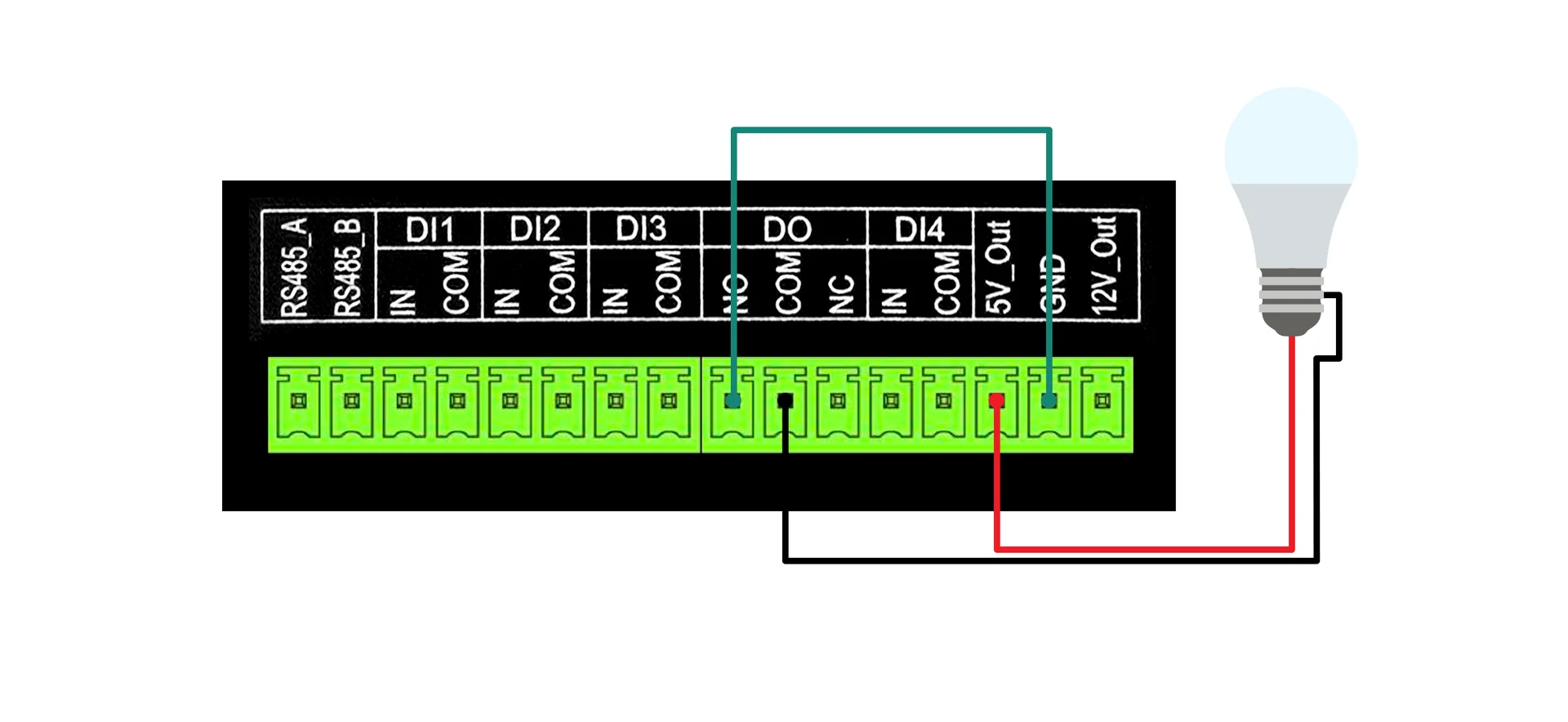 Figure 1: Wiring diagramNOTE
Ensure that 5V_Out is enabled in IO.Box before operating the DO channel.
When the Output State is set to Enabled, the relay closes the connection between COM and NO, completing the circuit:
5V_Out → Bulb → COM → NO → GND
Current flows through the bulb, and the bulb turns ON.
When the Output State is set to Disabled, the relay opens the connection between COM and NO, interrupting the circuit. No current flows and the bulb remains OFF.
Digital Output Interface Configuration
- Connect Bridge IO Device to IO.Box.
- (Optional) Go to the System tab from the main menu. Enable the DC 5V Output.
NOTE
That the power output interface connected to the example sensor is enabled here. Please enable the power output interface that your sensor is actually connected to.
- Go to the DI/DO tab and locate the Digital Output section. Enable the channel to activate the output port.
- When the Output State is Enabled, the bulb is lit, and when it is Disabled, the bulb is off.
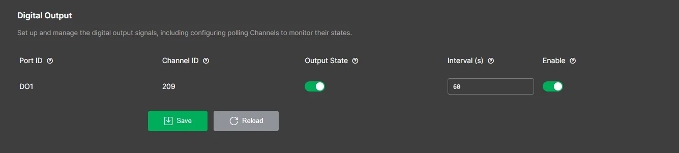 Figure 1: Output state
The relevant parameters are listed below. For more detailed descriptions of the parameters, refer to Digital Output.
- Port ID: Physical DO port. Auto-assigned and not editable.
- Channel ID: Output channel identifier used in control commands. Auto-assigned and not editable.
- Output State: Sets the output level (high/low). Writable.
- Interval (s): Reporting interval. Range: 5–86400 seconds. Default: 60.
- Enable: Enables or disables the output channel. Default: disabled.
Connect Bridge IO to LoRa Network Server for Uplink
This section provides you with operation guidance for connecting the Bridge IO to different LoRaWAN network servers and forwarding the collected data to the server (uplink).
Before connecting to the LNS, ensure that you have completed Configure LoRaWAN Parameters in IO.Box.
Built-in Network Server
In this section, the Bridge IO is connected to a RAKwireless gateway running WisGateOS 2, using the gateway's built-in LoRaWAN Network Server (LNS).
Set Up the Built-in Network Server
- Log in to the gateway Web UI. For instructions on how to access the Web UI, refer to the user guide for your gateway.
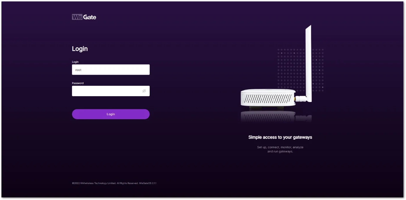 Figure 1: WisGateOS 2 login page
 - Once logged in, head to the LoRa menu.
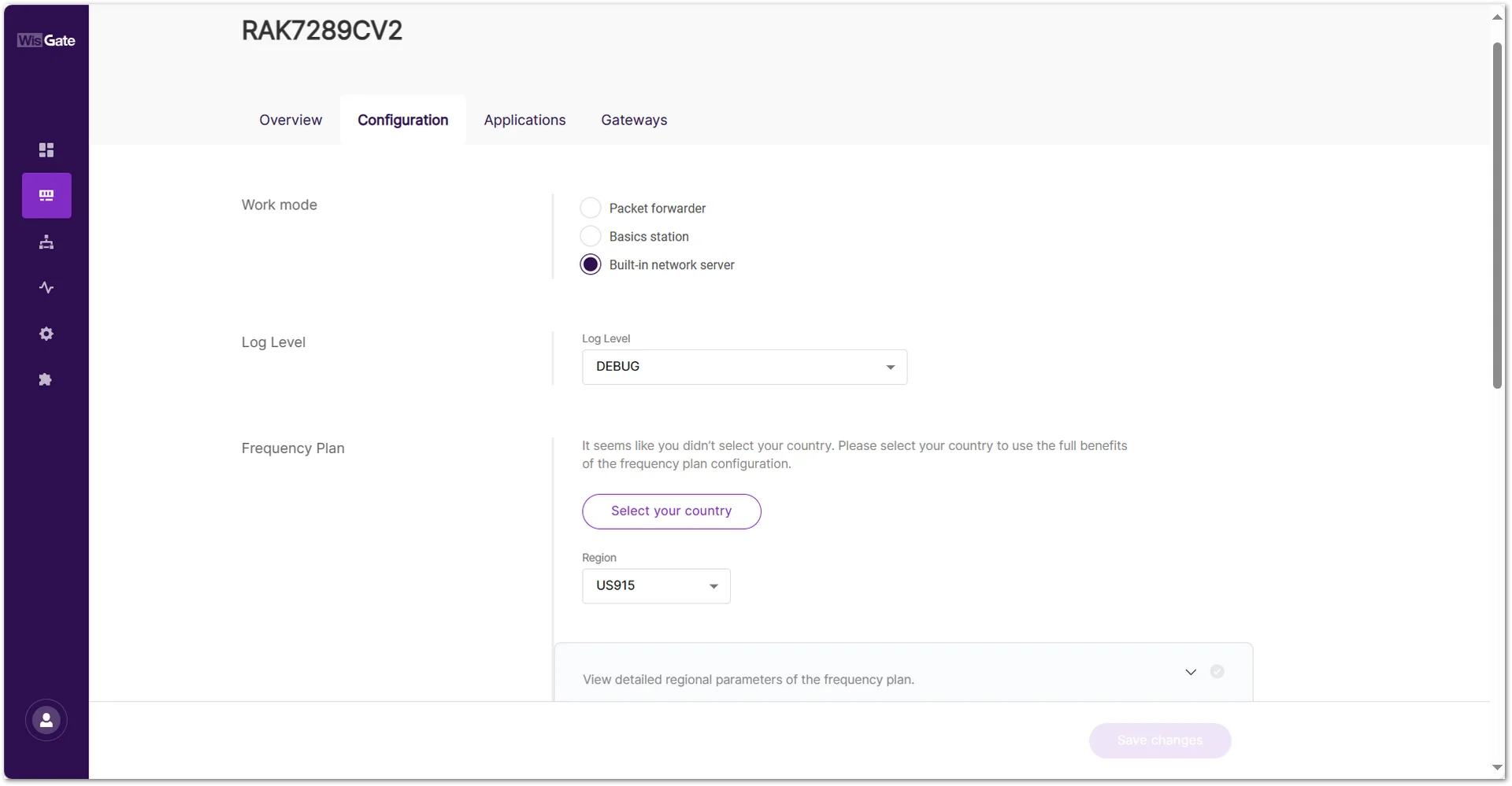 Figure 1: LoRa page
 - By default, the gateway works as a Built-In Network Server. If not, switch the Work mode to Built-in network server.
Create an Application
- Once the gateway is in Built-in network server mode, head to the Applications tab.
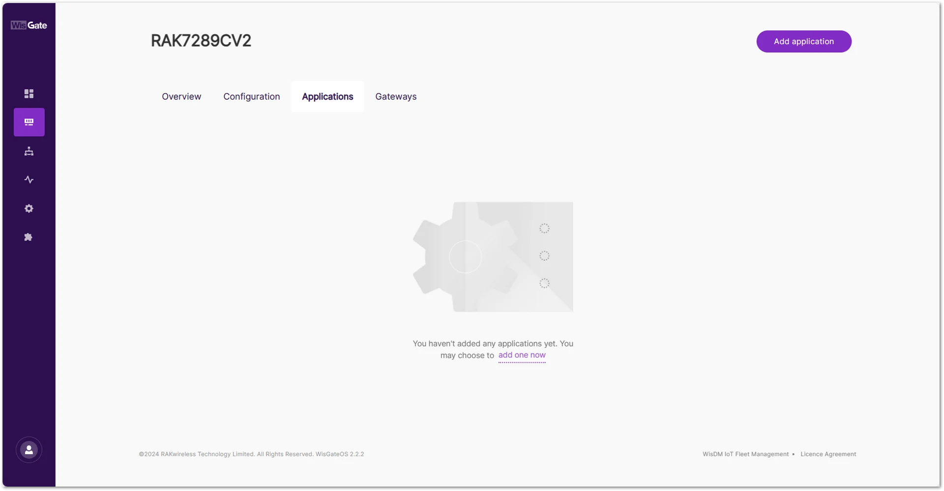 Figure 1: Create Application in the Built-In Network Server
 - Click the Add application button or add one now link to add a new application. On the new page, fill in the following information:
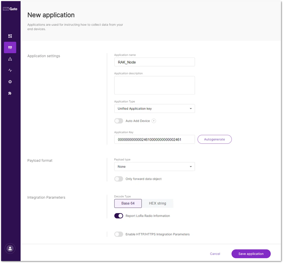 Figure 1: Adding application
- Application name: Type a name for the application.
- Application Type: Select the application type from the drop-down menu. In this document, choose Unified Application Key.
- Unified Application key: All devices use the same application key. After selecting this option, the Application Key field will appear. This value must match the one configured on the end device. You can manually enter the application key or click Autogenerate to generate one automatically.
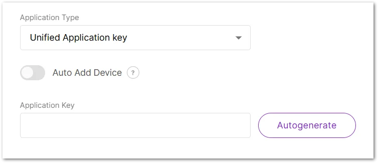 Figure 1: Unified application key
- Unified Application key: All devices use the same application key. After selecting this option, the Application Key field will appear. This value must match the one configured on the end device. You can manually enter the application key or click Autogenerate to generate one automatically.
The Auto Add Device switch activates the Application EUI field. The device will be automatically added to the application after the application EUI and key verification.
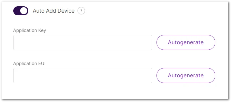 Figure 1: Auto add device
- Payload type: From the drop-down, select CayenneLPP payload type and turn on the Only forward data object feature.
- Once set, click Save application to add the application.
- After the application is added, head to the End devices tab. The devices should automatically register upon join request if you are using the Auto Add Device feature. If that’s not the case, click the Add end device button. On the End device information page fill in the following information:
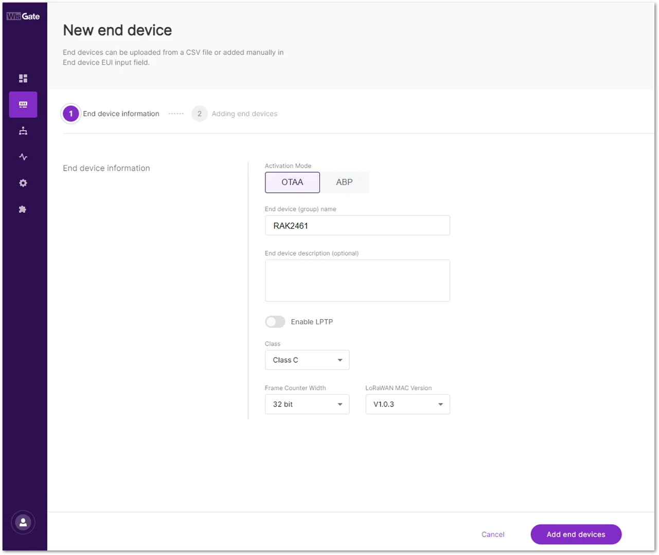 Figure 1: Successfully created application
- Activation Mode: choose the activation mode of your device.
- OTAA: Selected in this document.
- ABP: This mode pops up two additional fields:
- Application Session Key
- Network Session Key
- End device (group) name: the name of the device.
- Class: the class of the device.
- Frame Counter width: the width of the frame counter. Leave it as default.
- LoRaWAN MAC Version: the LoRaWAN MAC version.
Add the Device
- Once everything is set, click Add end devices to go to the page and add the device.
- On the Adding end devices page, type the device EUI at the End Device EUI (main) and click Add to “End Devices list”.
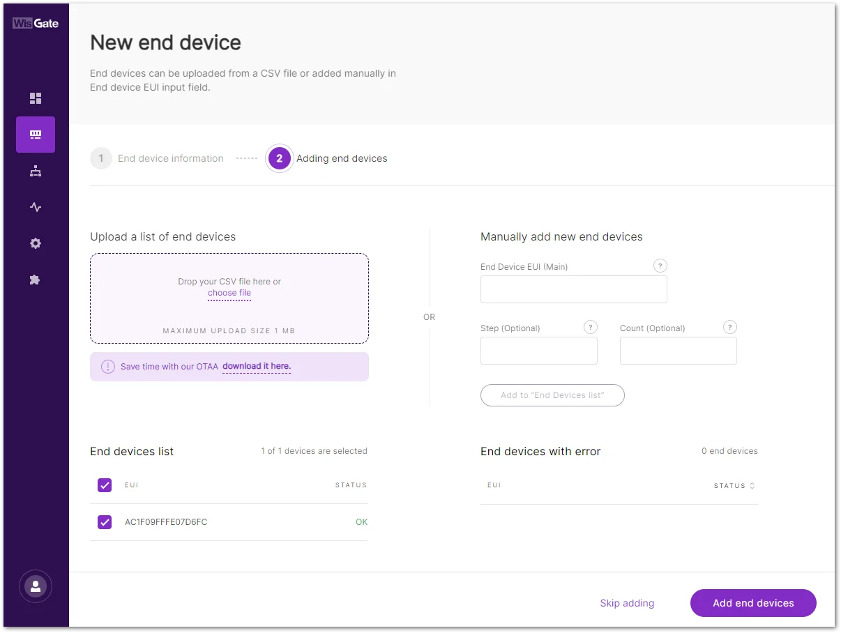 Figure 1: Adding end device
- If the EUI is correct, the device will show in the End devices list.
- If the EUI is not correct, the devices will show in the End devices with an error.
- Once the device is added to the End devices list, click Add end devices. Confirm you are adding the device.
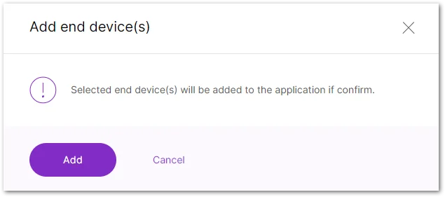 Figure 1: Confirmation message for adding a device
 - After the device has successfully joined the LNS, you will see the LoRaWAN status in the IO.Box console toggles as activated. You might need to refresh the page.
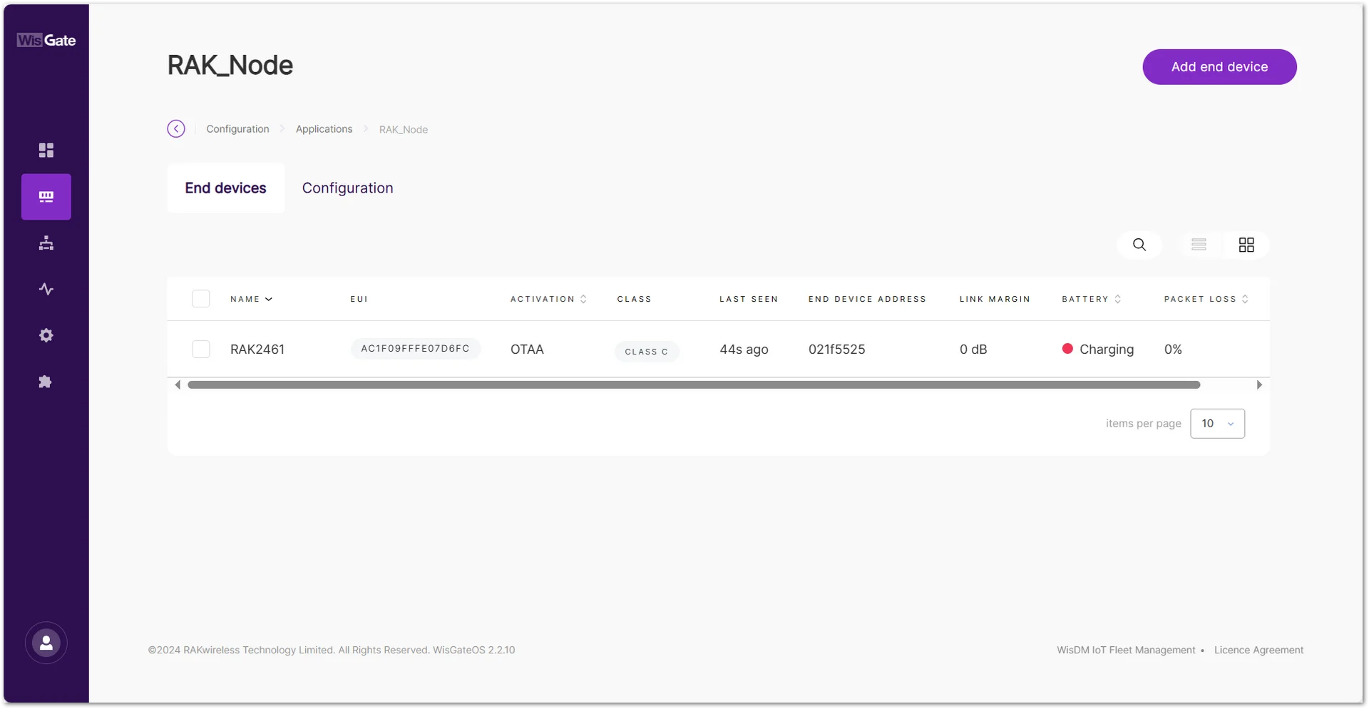 Figure 1: Device is online
 Figure 1: LoRaWAN status
Wait a while and you will see the uplink data from the LoRaWAN network.
The format of the uplink message is as follows:
0xD1   (Hex) = 209 (Dec)   → Channel ID
0x0100 (Hex) = 256 (Dec)   → DO OFF (Output Low)
0x0101 (Hex) = 257 (Dec)   → DO ON  (Output High)
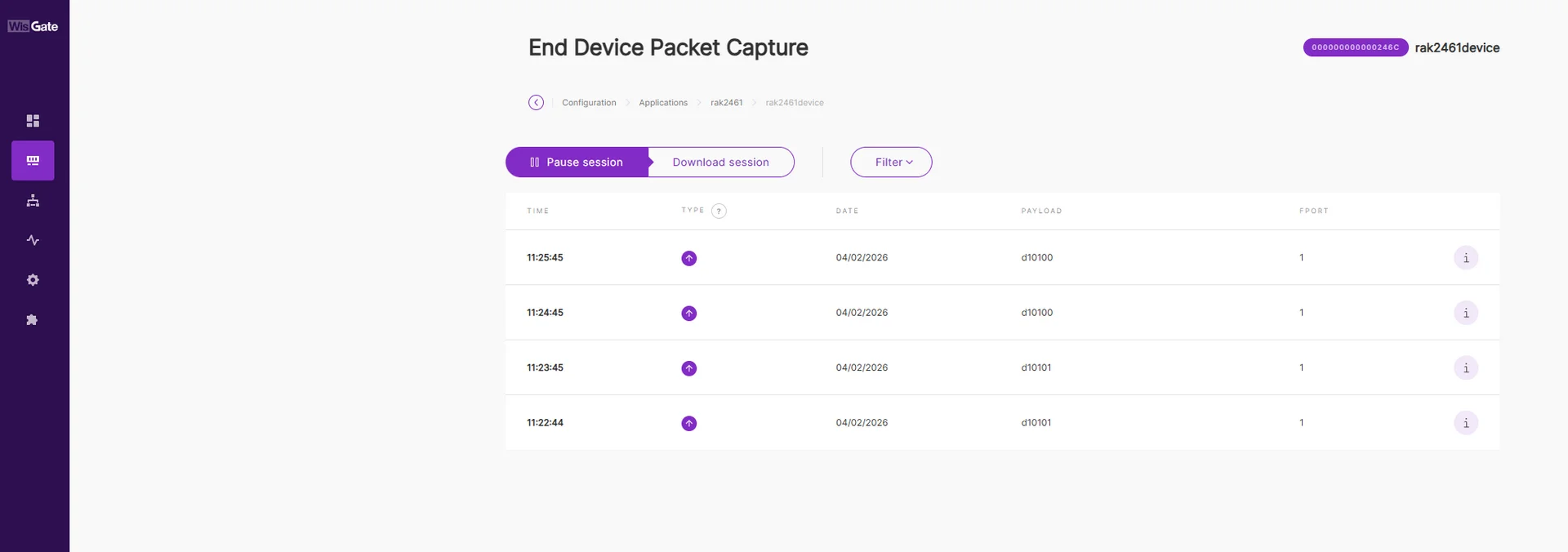 Figure 1: Uplink data
The Things Network (TTN)
Gateway Configuration
RAK gateways can connect to The Things Stack (TTN v3) using the following methods:
Packet Forwarder (UDP)
To connect a gateway to TTN v3 using Packet Forwarder (UDP), see How to Connect RAK Gateways to TTN v3 via UDP.
Basics™ Station (LNS)
To connect a gateway to TTN v3 using Basics™ Station (LNS), see How to Connect RAK Gateways to TTN v3 Using Basics™ Station (LNS).
Basics™ Station (CUPS)
To connect a gateway to TTN v3 using Basics™ Station (CUPS), see How to Connect RAK Gateways to TTN v3 Using Basics™ Station (CUPS).
Bridge IO Configuration
You can create applications and automatically register node devices on the TTN network server through IO.Box. For detailed configuration steps, refer to The Things Stack (TTN v3) Integration.
- After the device is created successfully, you can view the added device in the TTN.
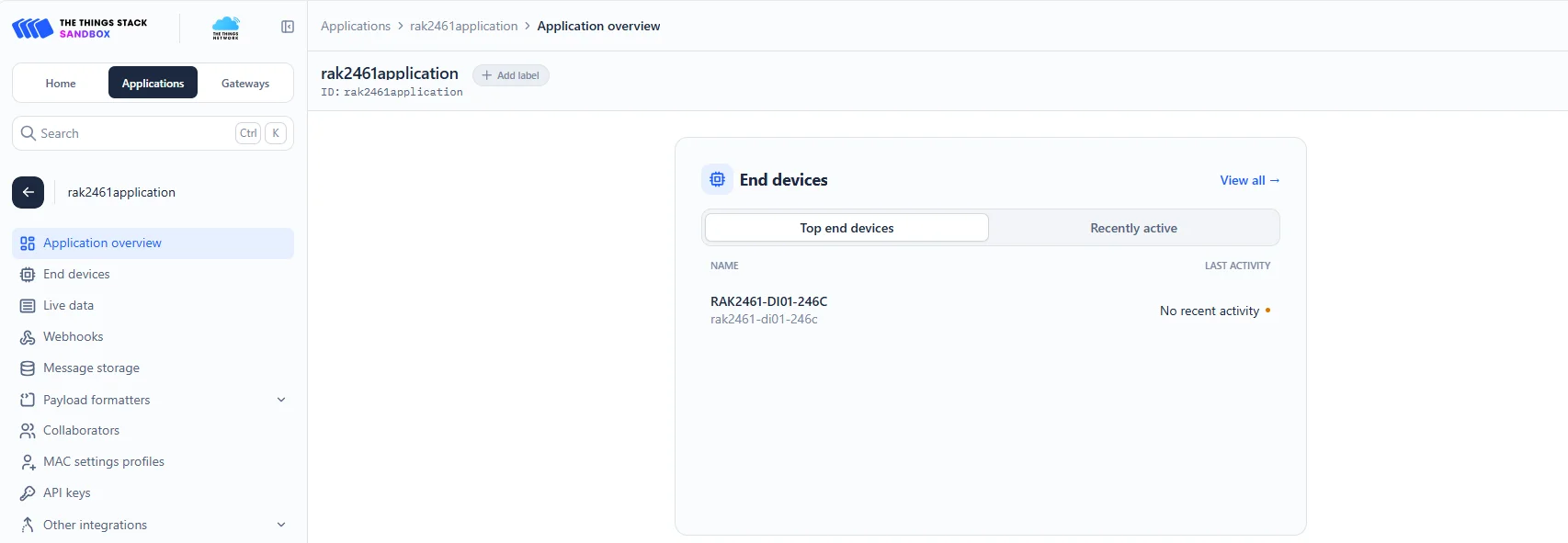 Figure 1: Added device in the TTN
 - To activate the device, click Apply.
 Figure 1: Active the device
 - After a successful Apply, the device in the TTN is activated and receives data as shown in Figure 62.
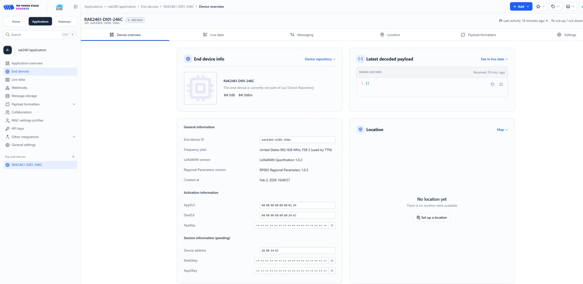 Figure 1: Device is online
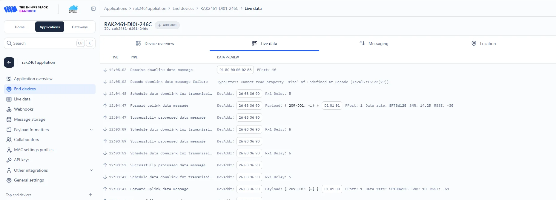 Figure 1: Data details
You will also see the LoRaWAN activation status in the IO.Box console enabled.
Figure 1: LoRaWAN statusChirpStack
This guide will show you how to connect the Bridge IO to a ChirpStack network server. In this tutorial, the ChirpStack v4 network server is used as an example.
Gateway Configuration
A gateway can be connected to the ChirpStack v4 server using the following methods:
Packet Forwarder (UDP)
To connect a gateway to ChirpStack v4 using Packet Forwarder (UDP), see How to Connect RAK Gateways to Chirpstack v4 via UDP.
Packet Forwarder (MQTT)
To connect a gateway to ChirpStack v4 using Packet Forwarder (MQTT), see How to Connect RAK Gateways to Chirpstack v4 via MQTT.
Basics™ Station (CUPS)
To connect a gateway to ChirpStack v4 using Basics™ Station (LNS), see How to Connect RAK Gateway to Chirpstack v4 Using Basics™ Station (LNS).
Bridge IO Configuration
You can create applications and automatically register node devices on the ChirpStack server through IO.Box. For detailed configuration steps, refer to ChirpStack v4 Integration.
- After the device is created successfully, you can view the added device in the ChirpStack.
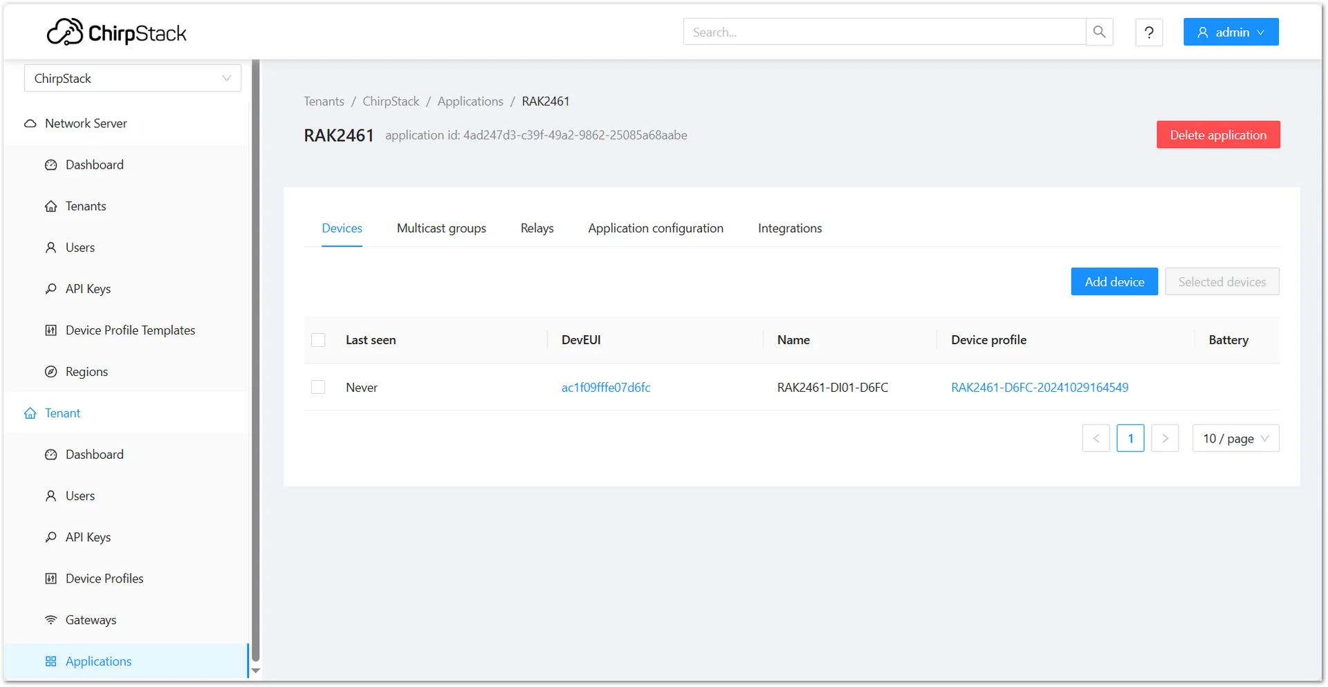 Figure 1: Added device in the ChirpStack
 - To activate the device, click Apply.
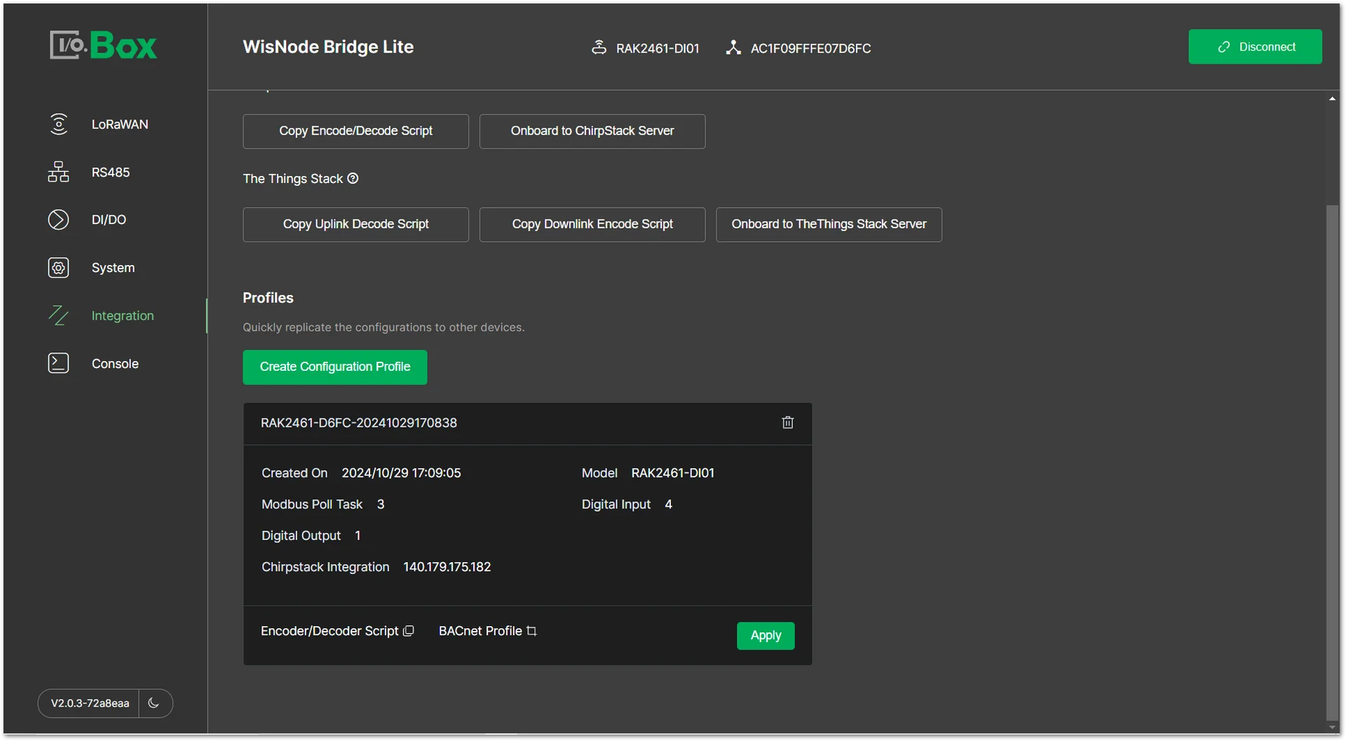 Figure 1: Active the device
 - After a successful Apply, the device in the ChirpStack is activated and receives data.
 Figure 1: Device is online
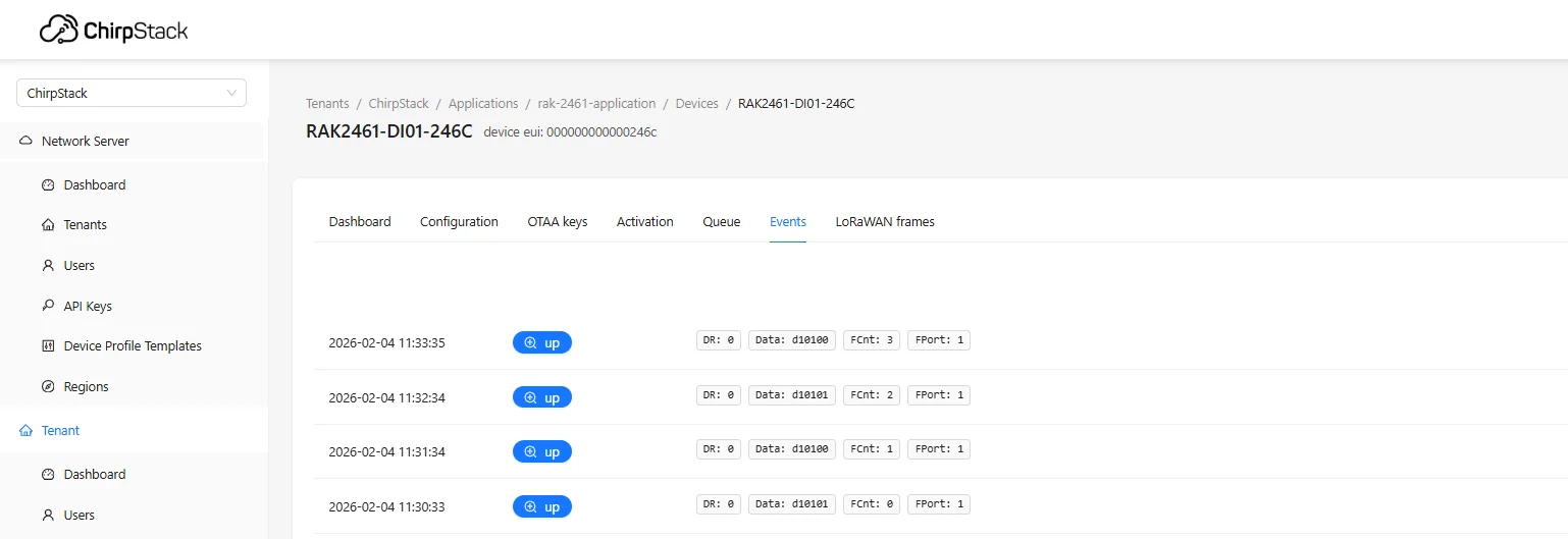 Figure 1: Data details
You will also see the LoRaWAN activation status in the IO.Box console enabled.
Figure 1: LoRaWAN status


