Downlink Commands and Uplink Data Format
This document describes the LoRaWAN® uplink data and downlink commands supported by the RAK9105U PowerLink.
You can use this reference to:
- Control the RAK9105U switchable power outputs through LoRaWAN downlinks.
- Configure the periodic uplink reporting interval.
- Decode RAK9105U output status and software version.
- Decode RAK Battery Plus operating, capacity, health, fault, and warning data.
The uplink payload depends on the power source connected to the RAK9105U:
| Deployment | FPort | Reported Data |
|---|---|---|
| External 9–24 VDC power | 1 | RAK9105U output status and software version |
| RAK Battery Plus | 2 | Voltage, current, cycle count, remaining capacity, and SOC |
| RAK Battery Plus | 3 | Full-charge capacity, fault status, warning status, and battery mode |
| RAK Battery Plus | 4 | Temperature, SOH, battery status, output status, RAK9105U software version, and BMS boot version |
Downlink Command Reference
The RAK9105U operates as a LoRaWAN Class C device and can receive downlink commands for power output control and uplink interval configuration.
The downlink examples in this document use a two-byte payload:
Power Output Control
Use the following commands to control the switchable outputs on the RAK9105U.
| Hex Payload | Description |
|---|---|
0000 | Turn OFF Output 3 - 5 V USB Type-C output |
0001 | Turn ON Output 3 - 5 V USB Type-C output |
0100 | Turn OFF Output 2 - controllable DC output |
0101 | Turn ON Output 2 - controllable DC output |
If the connected device, such as a gateway or router, contains internal capacitors, it may remain powered for several seconds after the output is turned off.
Uplink Interval Configuration
The RAK9105U periodically reports device or battery operating data after joining the LoRaWAN network.
Use the following downlink commands to configure commonly used reporting intervals:
| Hex Payload | Reporting Interval |
|---|---|
0201 | 1 minute |
021E | 30 minutes |
For a custom reporting interval, connect the RAK9105U to WisToolBox and execute the following command under ADVANCED > OPEN CONSOLE:
ATC+SENDFREQ=<interval>
The supported interval is 1–1440 minutes.
 Figure 1: Configure the uplink reporting interval
Uplink Data
After successfully joining the LoRaWAN network, the RAK9105U periodically reports uplink data.
The payload format depends on whether the RAK9105U is powered by a standard external DC source or connected to RAK Battery Plus.
External DC Power Uplink
When the RAK9105U is powered by a standard 9–24 VDC source, it reports basic device operating information through FPort 1.
The reported information includes:
- Output 2 and Output 3 status
- RAK9105U software version
FPort 1 - Device Status
Example:
FPort: 1
Payload: 036d
| Data Type | Length | Parameter | Raw Data | Parsed Data |
|---|---|---|---|---|
U8 | 1 Byte | Output status | 03 | Output 3 ON, Output 2 ON |
U8 | 1 Byte | RAK9105U software version | 6d | 1.0.9 |
Refer to Output Status for the output status definition.
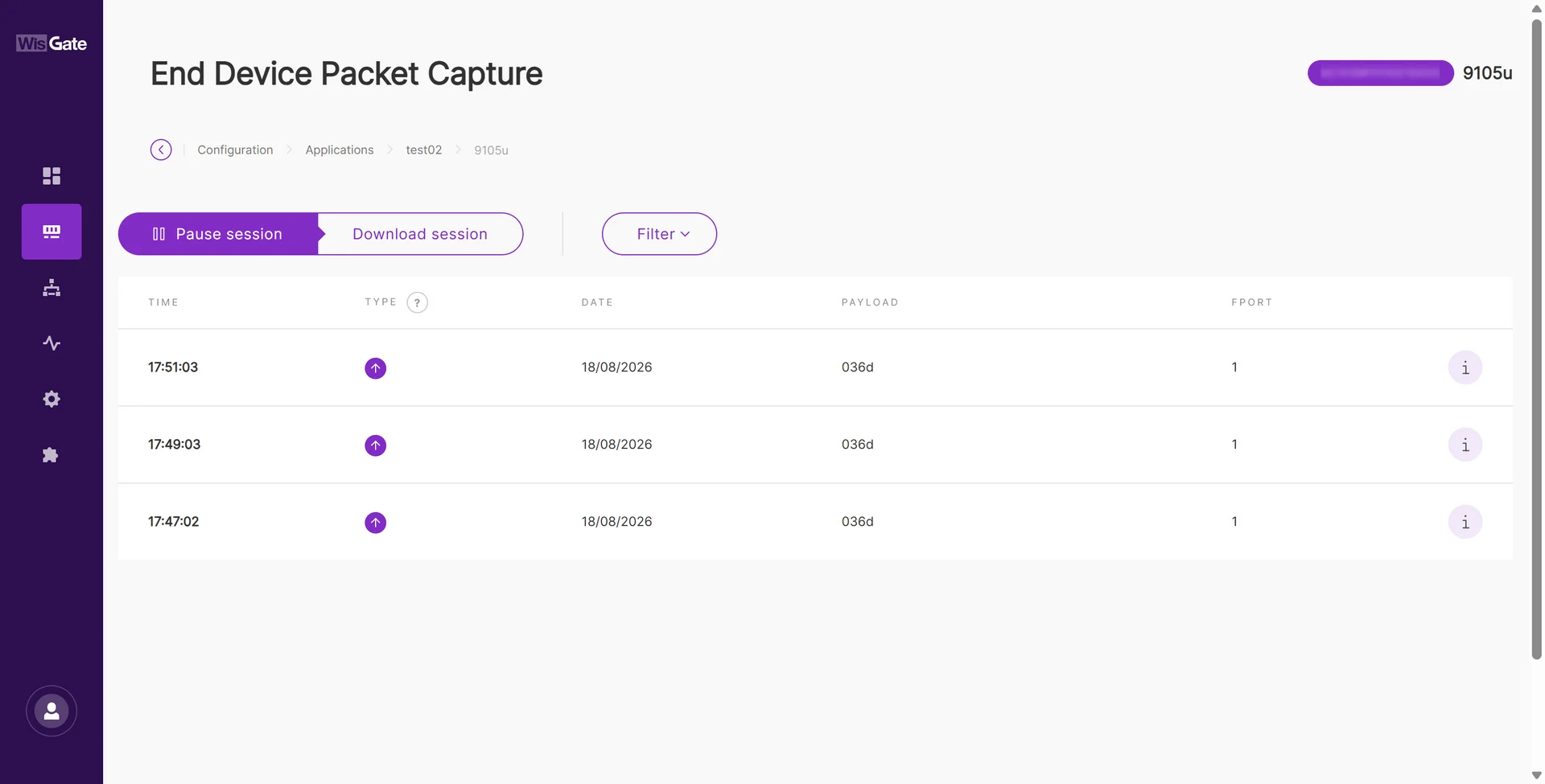 Figure 1: RAK9105U uplink packet
RAK Battery Plus Uplink
When RAK Battery Plus is connected to the Input DC 12V RS485 interface, the RAK9105U reads battery operating data through RS485 and periodically reports the data through LoRaWAN.
Battery information is distributed across FPorts 2, 3, and 4.
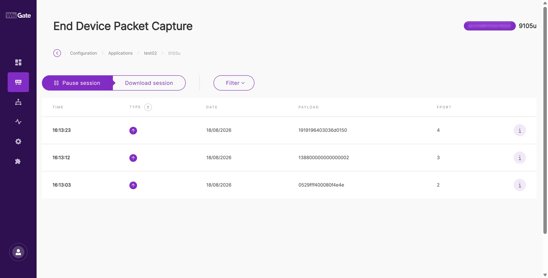 Figure 1: RAK9105U uplink packet
FPort 2 - Battery Operating Data
FPort 2 reports the primary real-time battery operating values.
Example:
FPort: 2
Payload: 0529fff400080f4e4e
| Data Type | Length | Parameter | Raw Data | Resolution / Unit | Parsed Value |
|---|---|---|---|---|---|
U16 | 2 Bytes | Current voltage | 0529 | 0.01 V | 13.21 V |
S16 | 2 Bytes | Current | fff4 | 0.01 A | -0.12 A |
U16 | 2 Bytes | Cycle count | 0008 | 1 cycle | 8 cycles |
U16 | 2 Bytes | Remaining capacity | 0f4e | 10 mAh | 39,180 mAh |
U8 | 1 Byte | State of charge (SOC) | 4e | 1% | 78% |
Based on the example payload:
- Voltage = 13.21 V
- Current = -0.12 A
- Cycle count = 8
- Remaining capacity = 39,180 mAh
- SOC = 78%
These values provide the main information required for routine Battery Plus monitoring.
FPort 3 - Battery Capacity and Status
FPort 3 reports battery capacity together with fault, warning, and operating mode information.
Example:
FPort: 3
Payload: 138800000000000002
| Data Type | Length | Parameter | Raw Data | Resolution / Description | Parsed Value |
|---|---|---|---|---|---|
U16 | 2 Bytes | Full-charge capacity | 1388 | 10 mAh | 50,000 mAh |
U16 | 2 Bytes | Fault status H | 0000 | Bit field; see Fault Status H | Normal |
U16 | 2 Bytes | Fault status L | 0000 | Bit field; see Fault Status L | Normal |
U16 | 2 Bytes | Warning status H | 0000 | Bit field; see Warning Status H | Normal |
U8 | 1 Byte | Battery mode | 02 | See Battery Mode | Discharging |
Based on the example payload, the full-charge capacity is 50,000 mAh, no reported fault or warning bits are active, and the battery is currently discharging.
FPort 4 - Battery Health and Device Status
FPort 4 reports battery temperature and health information together with RAK9105U operating status.
Example:
FPort: 4
Payload: 1919196403036d0150
| Data Type | Length | Parameter | Raw Data | Resolution / Description | Parsed Value |
|---|---|---|---|---|---|
S8 | 1 Byte | Average temperature | 19 | 1 °C | 25 °C |
S8 | 1 Byte | Maximum temperature | 19 | 1 °C | 25 °C |
S8 | 1 Byte | Minimum temperature | 19 | 1 °C | 25 °C |
U8 | 1 Byte | State of health (SOH) | 64 | 1% | 100% |
U8 | 1 Byte | Battery status | 03 | see Battery Status | Charge MOS ON, Discharge MOS ON |
U8 | 1 Byte | Output status | 03 | See Output Status | Output 3 ON, Output 2 ON |
U8 | 1 Byte | RAK9105U software version | 6d | Version encoding | 1.0.9 |
U8[2] | 2 Bytes | BMS boot version | 0150 | Version encoding | 1.80 |
Output Status
The output status field indicates the current states of the two remotely controllable RAK9105U outputs.
| Status Code | Output 3 - 5 V USB Type-C | Output 2 - DC Output |
|---|---|---|
00 | OFF | OFF |
01 | ON | OFF |
02 | OFF | ON |
03 | ON | ON |
Battery Mode
The Battery Mode field in FPort 3 indicates the current operating state of RAK Battery Plus.
| Code | Battery Mode |
|---|---|
0 | Null |
1 | Charging |
2 | Discharging |
3 | Fully Charged |
4 | Fully Discharged |
5 | Protect |
6 | Permanent Fail |
7 | Null |
Battery Status
The Battery Status field in FPort 4 indicates the current state of the battery MOSFETs and charge status.
| Bit | Parameter | Value Description |
|---|---|---|
| Bit 0 | Charge MOS status | 0: OFF 1: ON |
| Bit 1 | Discharge MOS status | 0: OFF 1: ON |
| Bit 2 | Reserved | - |
| Bit 3 | Fully charged | 0: Normal 1: Full |
| Bit 4 | Reserved | - |
| Bit 5 | Reserved | - |
| Bit 6 | Reserved | - |
| Bit 7 | Reserved | - |
Battery Fault and Warning Status
Battery fault and warning information is reported through bit-mapped fields in FPort 3.
For each defined bit:
0- Normal1- Corresponding fault or warning is active
Fault Status H
| Bit | Description |
|---|---|
| Bit 0 | Battery under-voltage protection |
| Bit 1 | Discharge over-current protection |
| Bit 2 | Discharge low-temperature protection |
| Bit 3 | Discharge high-temperature protection |
| Bit 4 | Discharge short-circuit protection |
| Bit 5 | Discharge over-current lock protection |
| Bit 6 | Charge over-voltage protection |
| Bit 7 | Charge over-current protection |
| Bit 8 | Charge low-temperature protection |
| Bit 9 | Charge high-temperature protection |
| Bit 10 | Charge short-circuit protection |
| Bit 11 | Charge over-current lock protection |
| Bits 12–15 | Reserved |
Fault Status L
| Bit | Description |
|---|---|
| Bit 0 | Voltage sampling AFE error |
| Bit 1 | Parameter configuration error |
| Bit 2 | Discharge MOS error |
| Bit 3 | Charge MOS error |
| Bit 4 | Voltage sampling line break error |
| Bit 5 | Temperature sampling line break error |
| Bit 6 | Reserved |
| Bit 7 | Balancing circuit error |
| Bit 8 | Reserved |
| Bit 9 | Charge high-temperature protection |
| Bit 10 | Reserved |
| Bit 11 | Reserved |
| Bits 12–15 | Reserved |
Warning Status H
| Bit | Description |
|---|---|
| Bit 0 | Under-voltage warning |
| Bit 1 | Over-voltage warning |
| Bit 2 | Discharge over-current warning |
| Bit 3 | Charge over-current warning |
| Bit 4 | Discharge low-temperature warning |
| Bit 5 | Discharge high-temperature warning |
| Bit 6 | Charge low-temperature warning |
| Bit 7 | Charge high-temperature warning |
| Bit 8 | Fully charged warning |
| Bit 9 | Reserved |
| Bit 10 | Reserved |
| Bit 11 | MOS high-temperature warning |
| Bit 12 | Reserved |
| Bit 13 | Reserved |
| Bit 14 | Reserved |
| Bit 15 | Low SOC warning |
Example Monitoring Data
For a Battery Plus deployment, the three uplink ports provide complementary information.
| Monitoring Requirement | Data | FPort |
|---|---|---|
| Battery level | SOC | 2 |
| Battery voltage | Current voltage | 2 |
| Charging/discharging current | Current | 2 |
| Battery usage history | Cycle count | 2 |
| Available capacity | Remaining capacity | 2 |
| Battery capacity | Full-charge capacity | 3 |
| Operating state | Battery mode | 3 |
| Fault monitoring | Fault status H / L | 3 |
| Warning monitoring | Warning status H | 3 |
| Battery temperature | Average / Maximum / Minimum temperature | 4 |
| Battery health | SOH | 4 |
| RAK9105U output state | Output status | 4 |
| RAK9105U software version | Software version | 4 |
| Battery BMS version | BMS boot version | 4 |


