Device Configuration
Device Info
After connecting a device with WisToolBox Desktop, select the device to access the available configurations and features.
The DEVICE INFO section provides information about the connected device.
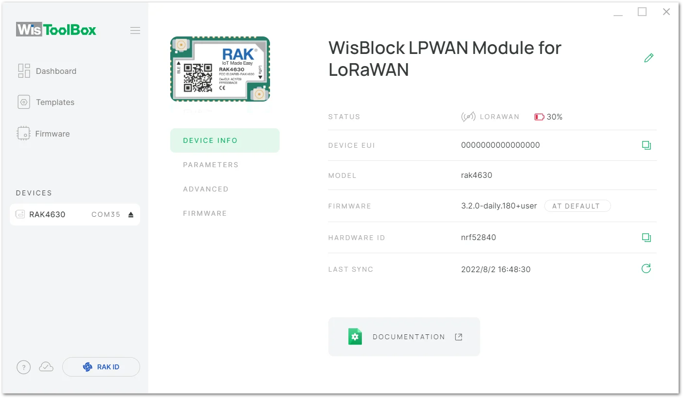 Figure 1: WisToolBox Desktop dashboard device info
- STATUS: shows the device network connection status, battery status, RSSI, and SNR
- DEVICE EUI: device EUI
- MODEL: device module's model
- FIRMWARE: device firmware version
- HARDWARE ID: hardware ID
- LAST SYNC: last sync time
To learn more about the device connected to WisToolBox, you can click the DOCUMENTATION button at the bottom of the dashboard.
Parameters
The WisToolBox parameters are categorized into seven (7) sections:
- Global Settings
- LoRaWAN Keys, ID, EUI
- Data on LoRa Network
- LoRa Network Management
- Generic LoRaWAN instructions
- LoRaWAN Multicast Group
- Custom Fields
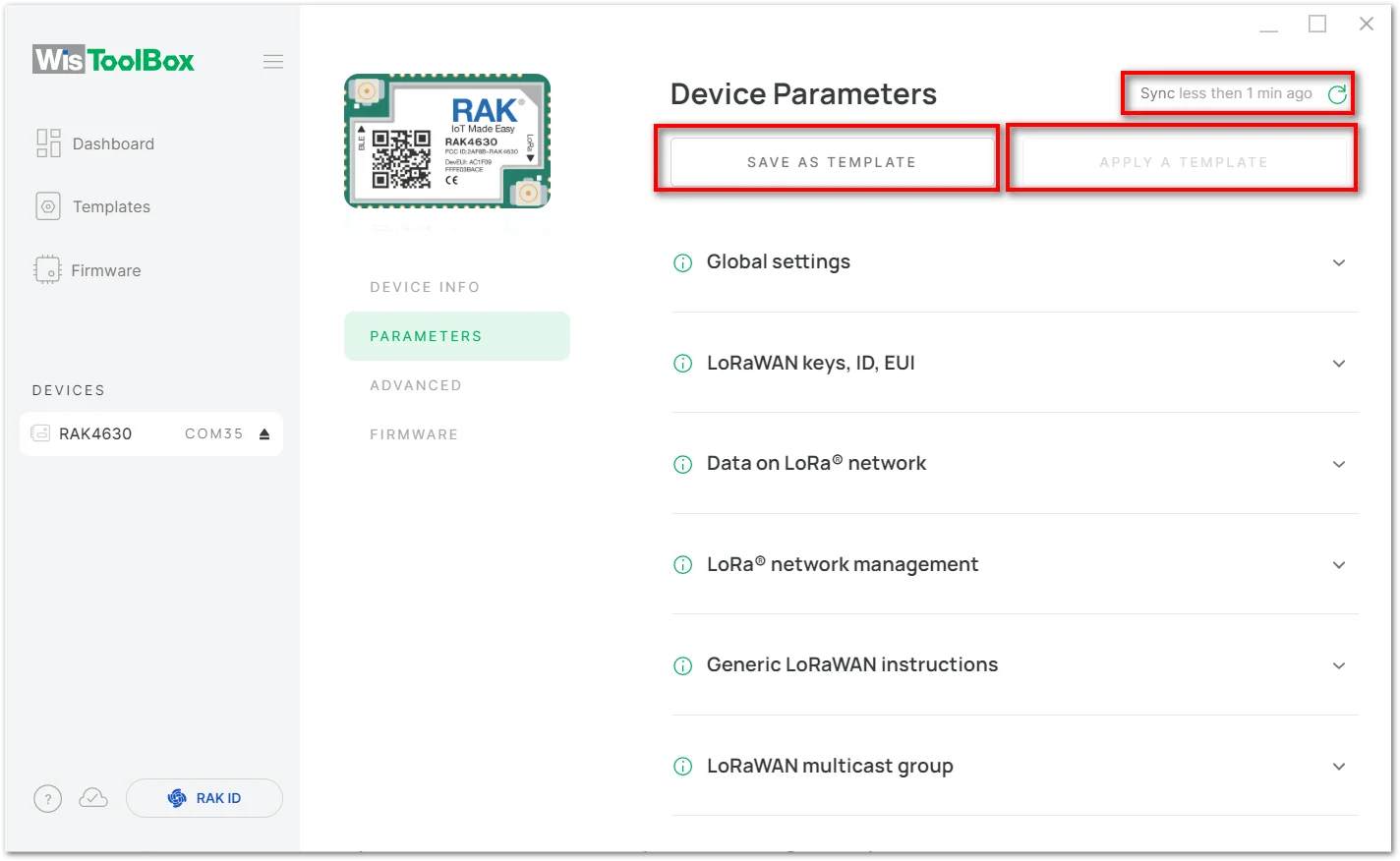 Figure 1: WisToolBox Desktop dashboard parameters
-
SYNC ICON: During the configuration process, if the configuration parameters in the tool have not been updated yet, click the synchronization icon highlighted on the upper right will refresh the data and get the latest AT command return values if the tool shows no updated values.
-
SAVE AS TEMPLATE: After the custom device configuration is complete, you can click this button to save the parameters as a configuration template.
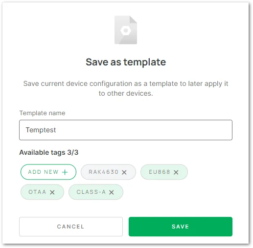 Figure 1: Save a Template
To save a template, follow the steps below:
-
Template Name: enter your desired template name. -
Available tags: add tags to the template, up to three can be selected. -
When done, click the "SAVE" button.
- APPLY A TEMPLATE: when configuring a new device, a saved configuration template can be selected here and applied to the new device. This function can only be used after saving the template.
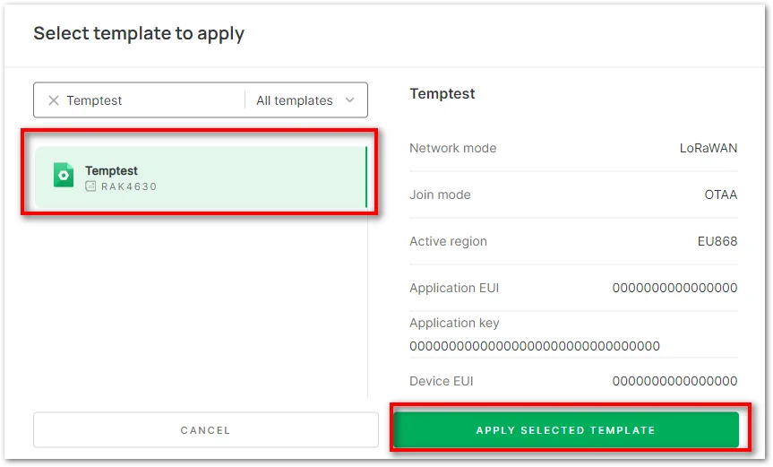 Figure 1: Apply a Template
To apply a template, follow the steps below:
- In the search bar, enter the name of the template you want to select.
- In the list of search results, click the template of your choice.
- Click the "APPLY SELECTED TEMPLATE" button to apply this template to the new device configuration.
Global Settings
Configure the following parameters:
- Network Mode: Optional LoRaWAN / P2P settings.
- Join Mode: The LoRaWAN join method of the end device, OTAA or ABP.
- Active Region: Available frequency bands include CN470, EU433, RU864, IN865, EU868, US915, AU915, KR920, and AS923.
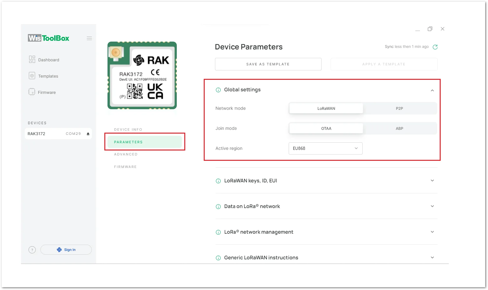 Figure 1: WisToolBox Desktop dashboard global parameters
LoRaWAN Keys, ID, EUI
Configure the following parameters:
Application EUI: The APPEUI parameter of the LoRaWAN network server must be the same as the device. It can be obtained from the LoRaWAN network server after configuration, or you can also customize 16 hexadecimal values here and apply the customized Application EUI to the LoRaWAN network server.Application Key: The APPKEY parameter of the LoRaWAN network server must be the same as the device. It can be obtained from the LoRaWAN network server after configuration, or you can also customize 32 hexadecimal values here and apply the customized Application KEY to the LoRaWAN network server.Device EUI: The DEVEUI parameter of the LoRaWAN network server must be the same as the device. It can be obtained RAK module sticker and must be applied to the DEVEUI of the LoRaWAN network server and also to the device via WisToolBox.
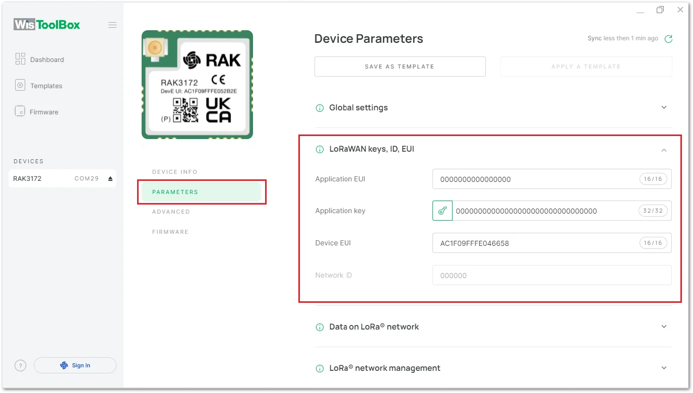 Figure 1: WisToolBox Desktop dashboard LoRaWAN keys, ID, and EUI parameters
Data on LoRa Network
Configure the following parameters as required:
Confirm Mode: Message confirmation mode.Join network: Enables joining the network.Automatic access: Whether to enable automatic access to the network, after the module is powered on, it will automatically join the network.Reattempt period (s): Indicates the network retry period, the value is 7~255 (in seconds), and the default value is 8.Max number of reattempts: Indicates the maximum number of retries, the value is 0~255, and the default value is 0.
When done, click "SAVE AND SEND".
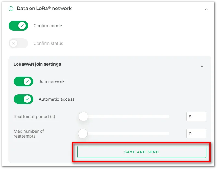 Figure 1: Network Access settings
Before sending the network access command, make sure that the device is already registered to the LoRaWAN Network Server and has access to the connected LoRaWAN Gateway.
Network Status: After successful network access, you can see that "Network status" is enabled.Last received data: View the last data received by the device.Send data: Configure the port number and send data to send uplink data to the gateway.
Click "SEND" after completion.
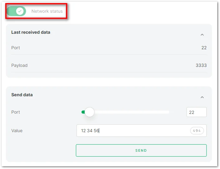 Figure 1: Send Data settings
LoRa Network Management
Configure the following parameters:
ADR: Adaptive Data Rate.CLASS: Device working mode. Class A / Class B / Class C.Duty Cycle: Duty cycle.Data rate: The data rate.Public network mode: Public network mode.RX1 delay: Receive window 1 delay.RX2 data rate: The data rate of receive window 2.RX2 delay (s): Receive window 2 delay.Transmit power: Transmit power.
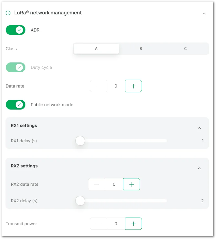 Figure 1: LoRa Network Management
Generic LoRaWAN Instructions
The following functions are available:
- Long packet data
Port: The application port to transfer.Ack: Whether to open the confirmation package.Payload: String in hexadecimal format.
- RSSI query: View received RSSI.
- Network link check: Network link status.
0: Disable link checking.1: Perform a link check.2: The module will automatically perform a link check after each upload of data.
- Confirm packet retransmission: Confirm packet retransmission. The parameter range is 0~7.
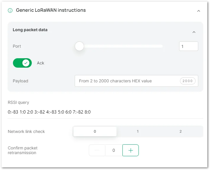 Figure 1: Generic LoRaWAN Instructions
LoRaWAN Multicast Group
This function can be used to create a multicast group, and the supported device working mode is Class B or Class C.
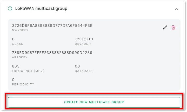 Figure 1: Create Multicast group
To create a new multicast group, configure the following parameters:
Class: device working mode, Class B or Class C.DevAddr: the device address to add.NwkSKey: network session key.AppSKey: application session key.Frequency (MHz): enter the frequency within the frequency band.Datarate: the data rate.
After that, click "CREATE GROUP"
The parameters in the multicast group must be the same as the ones in the LoRaWAN network server.
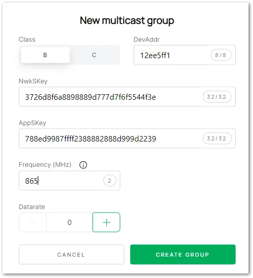 Figure 1: Configuring Multicast group
Custom Fields
This option is displayed if the device firmware is a custom firmware. Custom AT commands can be read and sent in the function options.
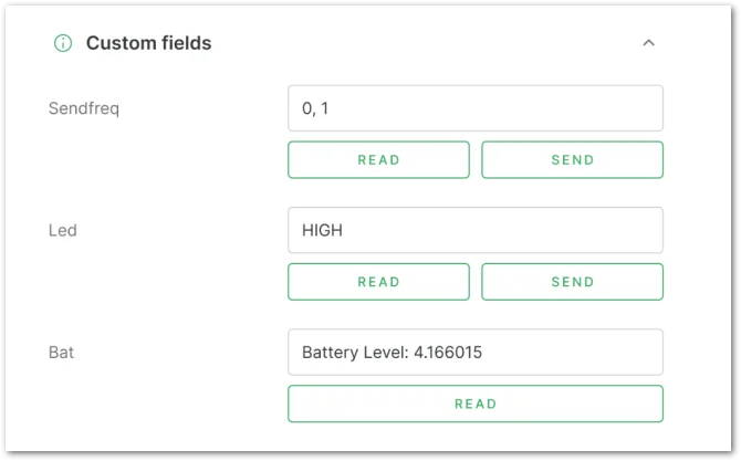 Figure 1: Custom command field
Apply Command
If you change the value of any parameter, then the APPLY COMMAND button will appear. Click the button to update the new value on the RAK device.
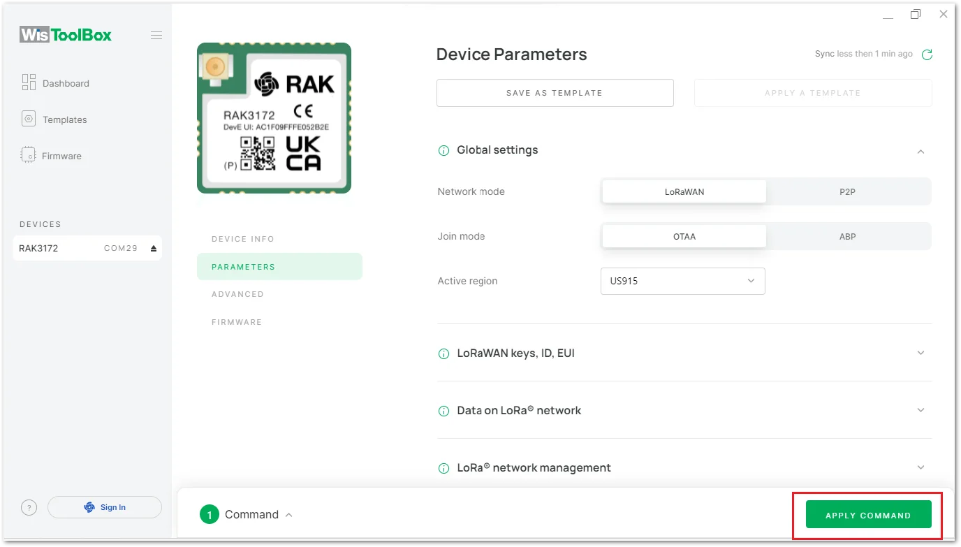 Figure 1: WisToolBox Desktop dashboard apply command
After the command is applied successfully, click CLOSE to return to the Dashboard.
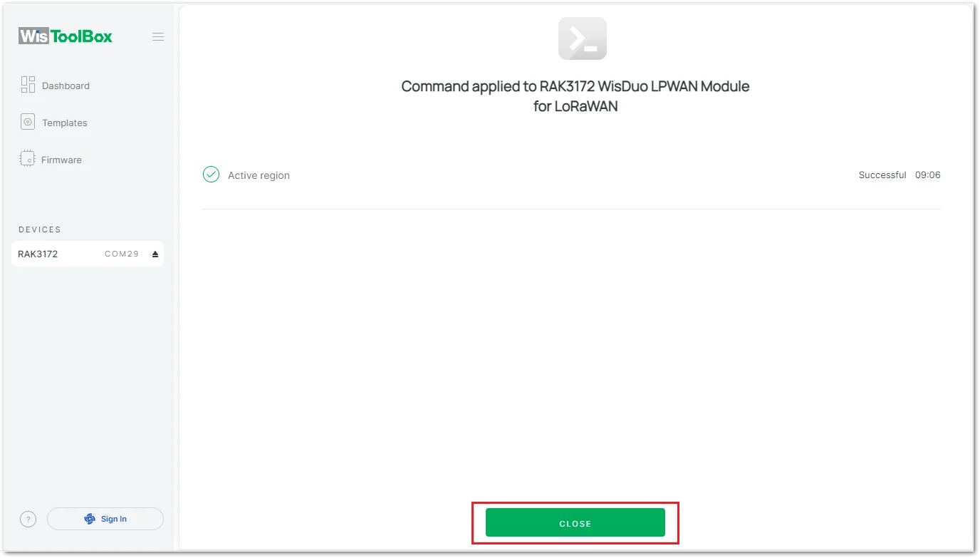 Figure 1: WisToolBox Desktop dashboard apply command result
Advanced
- The ADVANCED option allows access to the RAK module ADVANCED commands. From the dashboard menu, select the installed module.
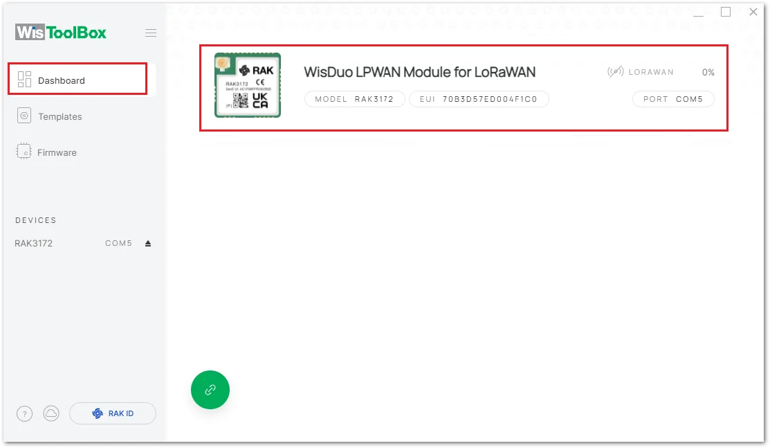 Figure 1: WisToolBox Desktop connected device
- Then click the ADVANCED option.
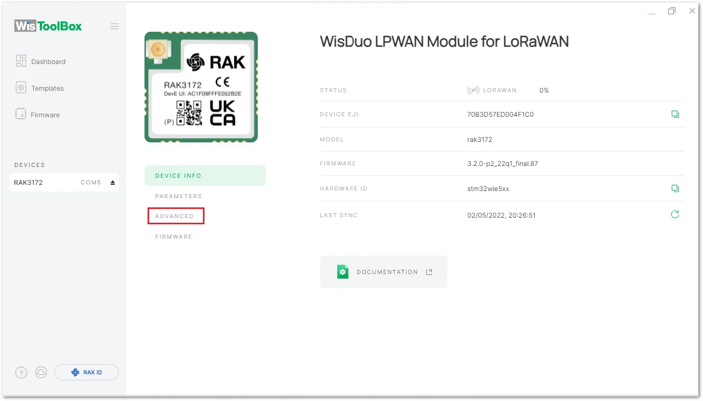 Figure 1: WisToolBox Desktop module details
- The following Advanced commands are available:
Sleep mode: Enable sleep mode. After setting the sleep time, click "SAVE".RESTORE TO FACTORY SETTINGS: Restore factory settings.MCU RESET: Reset the device.OPEN CONSOLE: Open the console, where you can send AT commands and view the return value of the device AT commands.
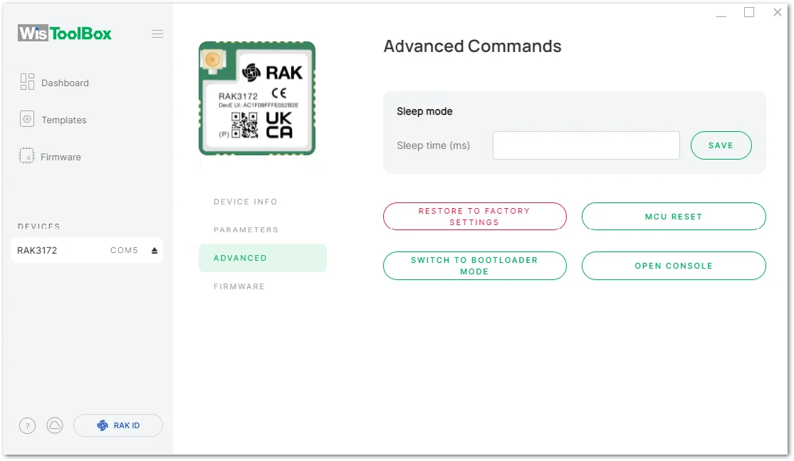 Figure 1: WisToolBox Desktop advanced commands


