Battery Plus Monitoring and Remote Power Control
This guide explains how to deploy the RAK9105U PowerLink together with RAK Battery Plus.
In this setup, the RAK9105U is connected to Battery Plus through the Input DC 12V RS485 interface. The connection provides both power and RS485 communication, allowing the RAK9105U to periodically read Battery Plus operating data and report it through LoRaWAN®.
The RAK9105U can also remotely switch the power supplied to a connected gateway or other device through its controllable outputs.
Prerequisites
Package Contents
- 1 × RAK9105U PowerLink
- 1 × Power Cable with 4-Pin Terminal Block
- 1 × USB Type-C cable
- 2 × DC power cables
Additional Requirements
- RAK Battery Plus
- Computer with WisToolBox installed
- LoRaWAN gateway within radio range
- Access to a compatible LoRaWAN Network Server
Configure the RAK9105U
Before completing the final hardware installation, configure the RAK9105U and verify its LoRaWAN connection through the USB Console interface.
Connect the RAK9105U to a Computer
- onnect the Console port of the RAK9105U to your computer using a USB Type-C cable.
- Open WisToolBox.
- Click START to detect connected devices.
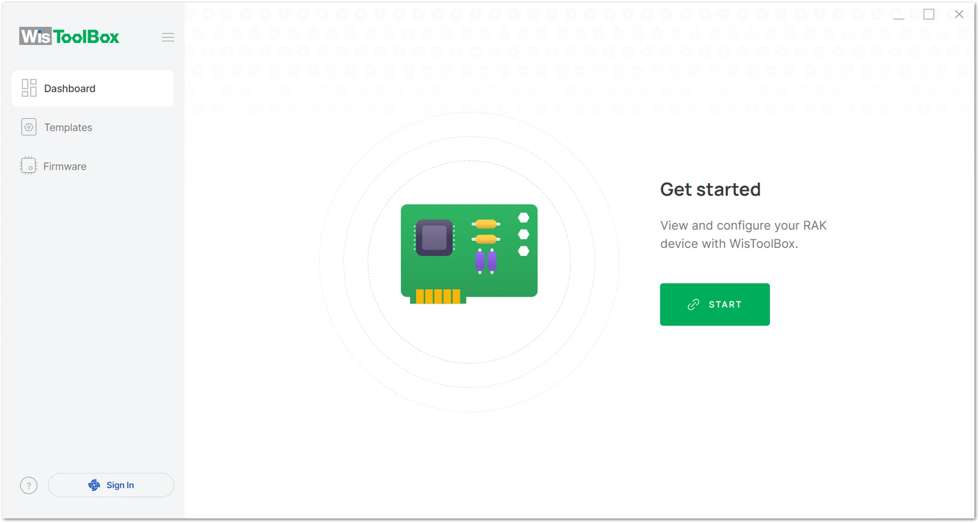 Figure 1: Start device detection in WisToolBox
 - After the device is detected, click CONNECT.
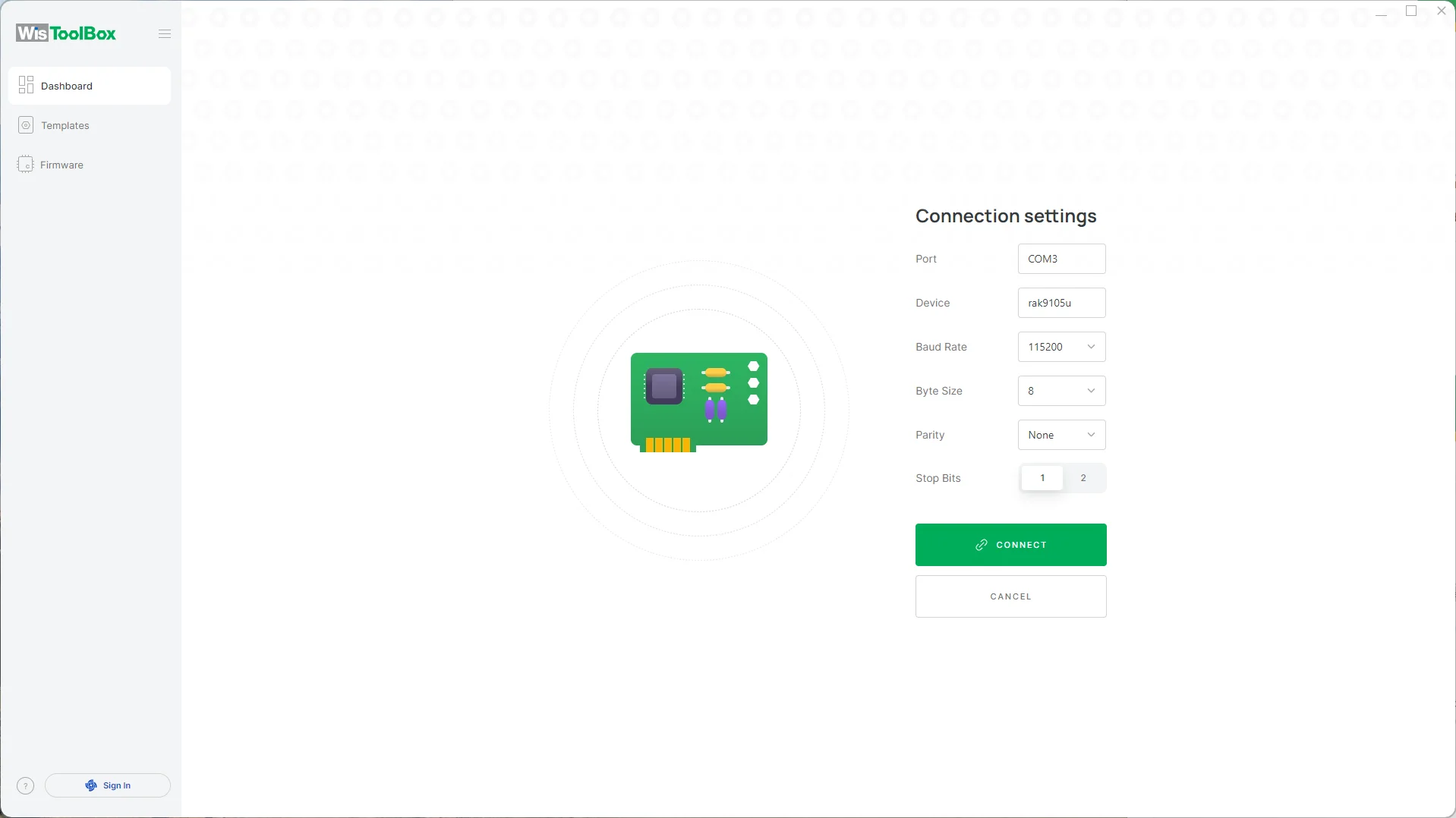 Figure 1: Connect the RAK9105U in WisToolBox
 - Select the detected device to open its configuration page.
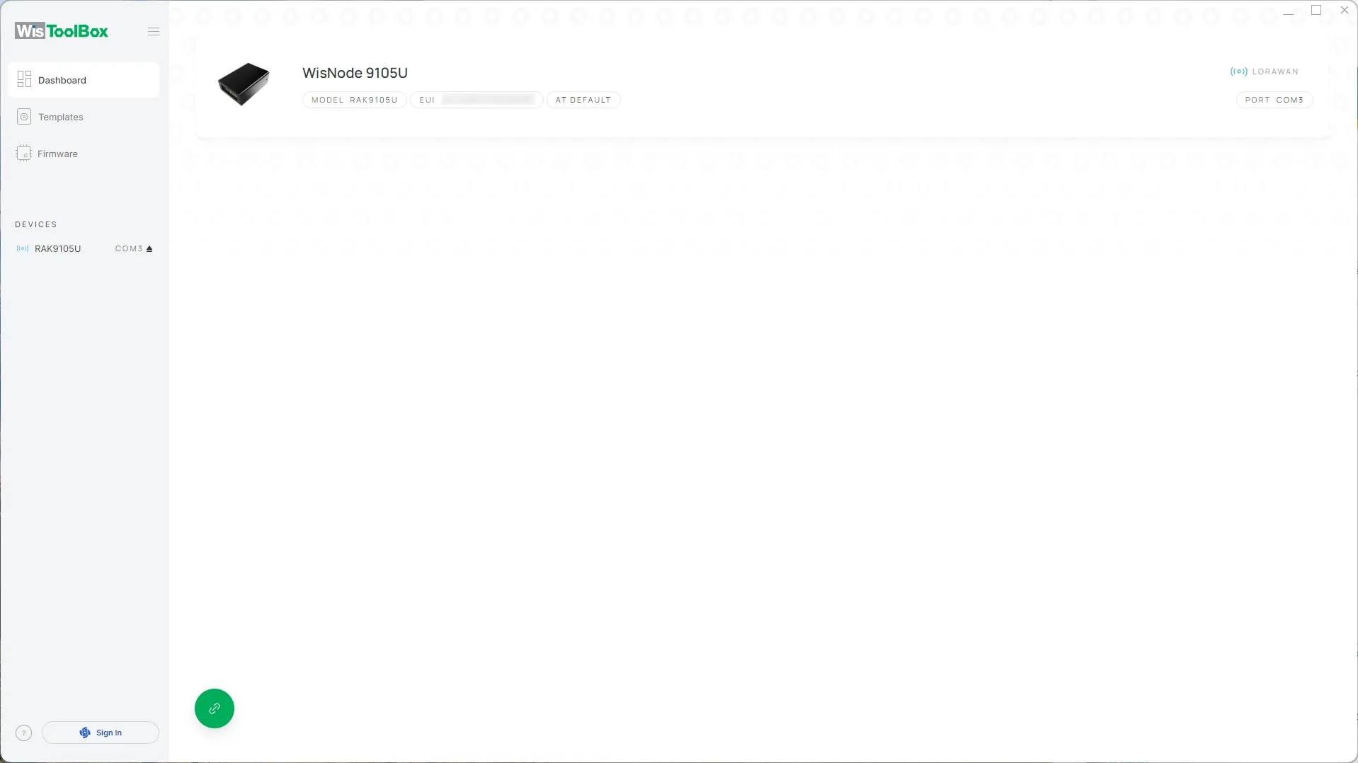 Figure 1: Open the RAK9105U device configuration
Configure LoRaWAN Parameters
Configure Global Settings
In PARAMETERS > Global Settings, configure:
- Join mode: OTAA (Default, non-configurable)
- Active region: Select the frequency region used by your gateway and Network Server.
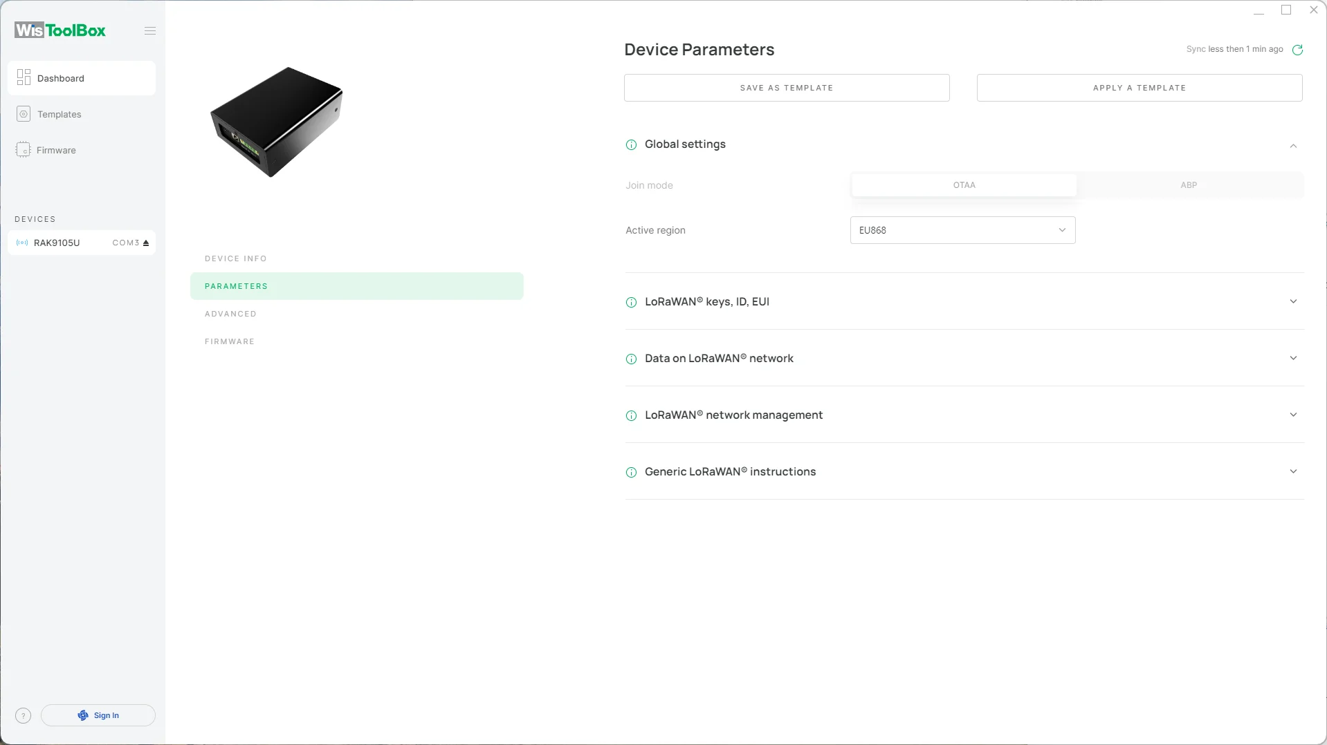 Figure 1: Configure LoRaWAN global settings
The RAK9105U supports OTAA activation. The configured frequency region must match the frequency plan used by the gateway and Network Server.
Configure LoRaWAN Credentials
Go to LoRaWAN Keys, ID, EUI and configure or record:
- Application EUI
- Application Key
- Device EUI
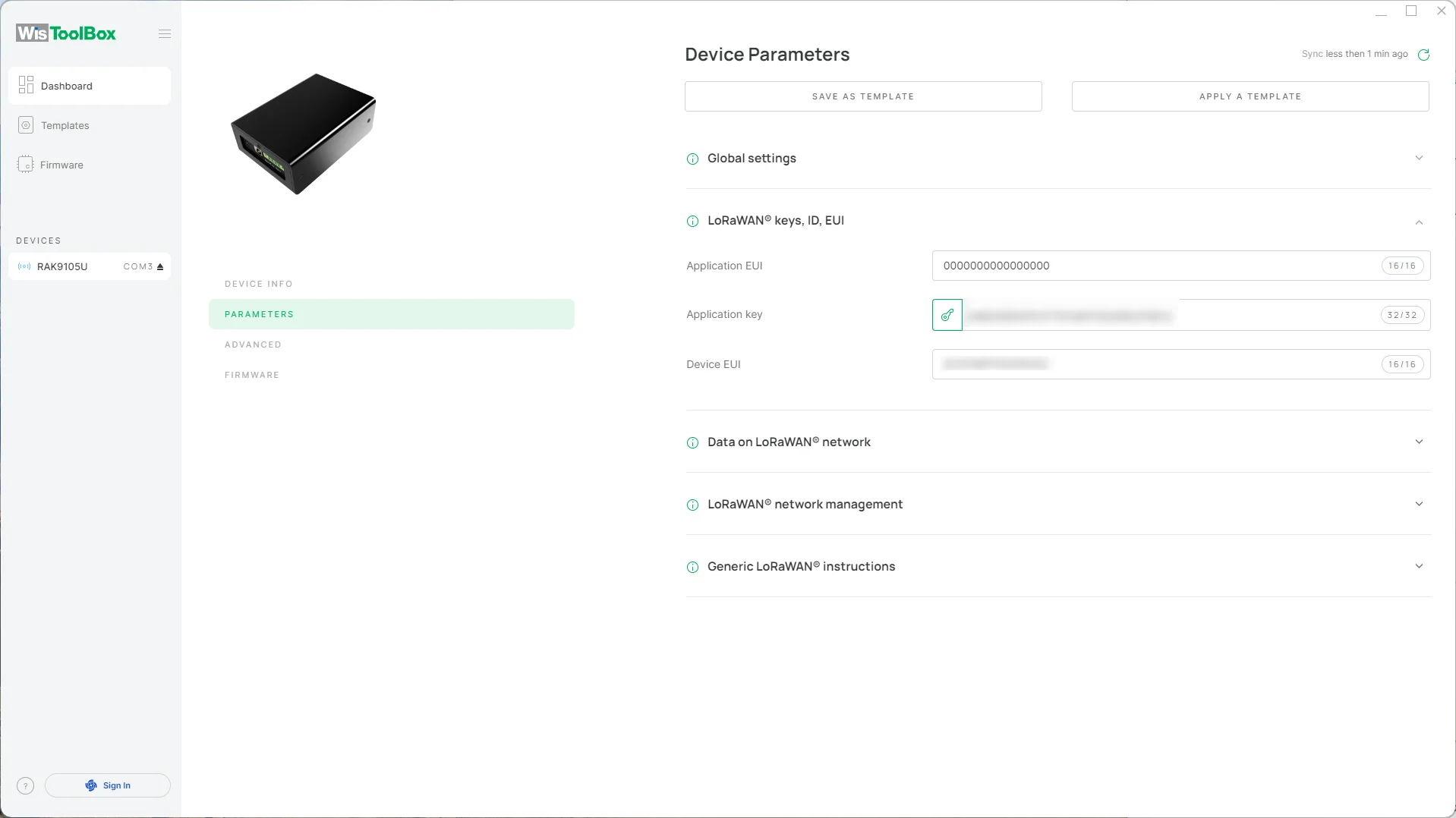 Figure 1: Configure LoRaWAN credentials
The DevEUI, AppEUI, and AppKey configured on the RAK9105U must match the corresponding values registered on the LoRaWAN Network Server.
Mismatched credentials will prevent the device from joining the network.
Click APPLY COMMAND to apply the configuration.
 Figure 1: Apply the RAK9105U configuration
Connect to a LoRaWAN Network Server
Choose one Network Server according to your deployment.
The following examples assume that a compatible LoRaWAN gateway is already deployed and connected to the selected Network Server.
RAK Built-in Network Server
This section uses the Built-in Network Server available on a RAKwireless WisGate gateway.
Enable the Built-in Network Server
- Log in to the WisGateOS 2 Web UI.
- Navigate to LoRa.
- Set Work Mode to Built-in Network Server.
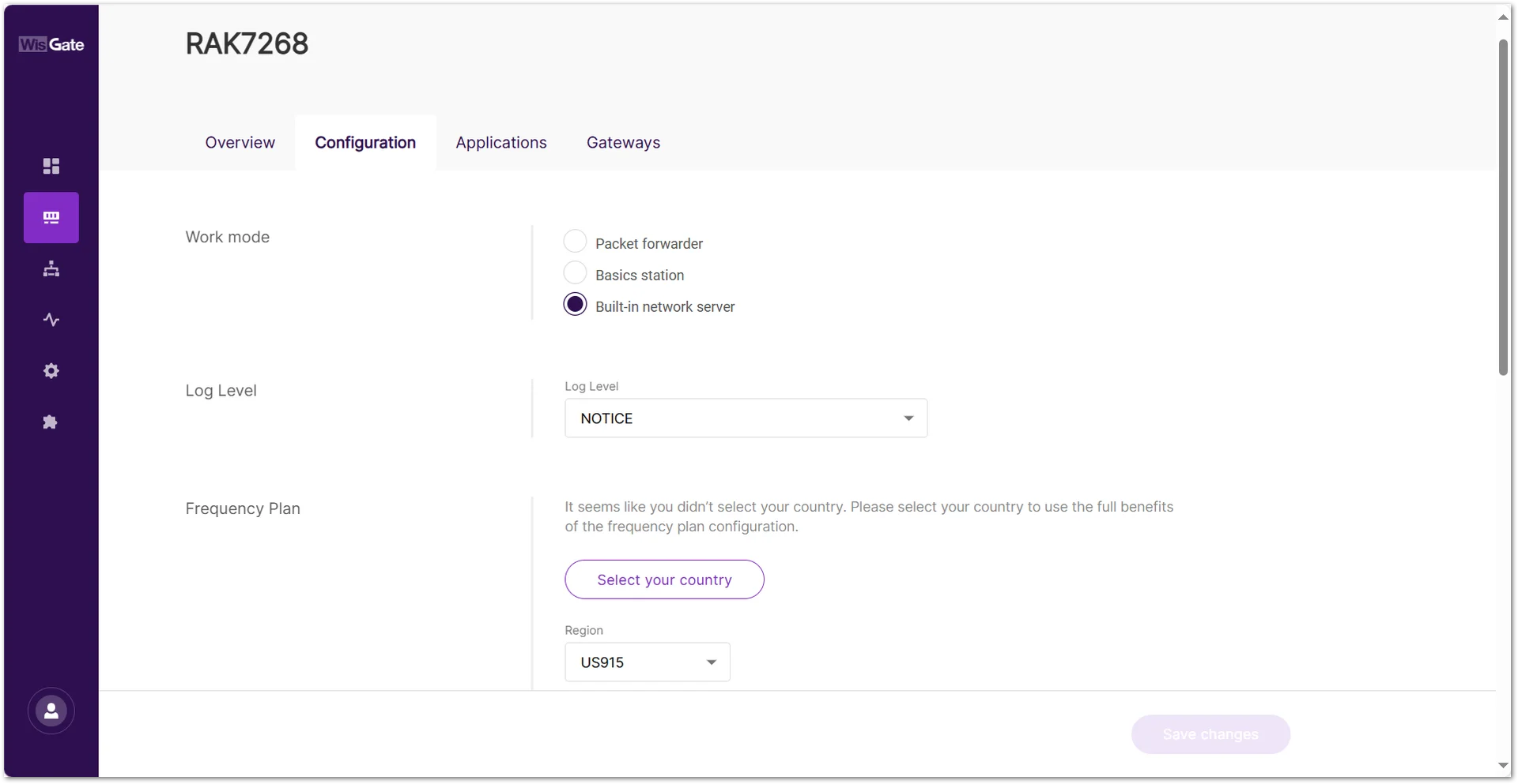 Figure 1: Configure Built-in Network Server mode
Create an Application
- Go to Applications.
- Click Add application.
- Configure the application settings.
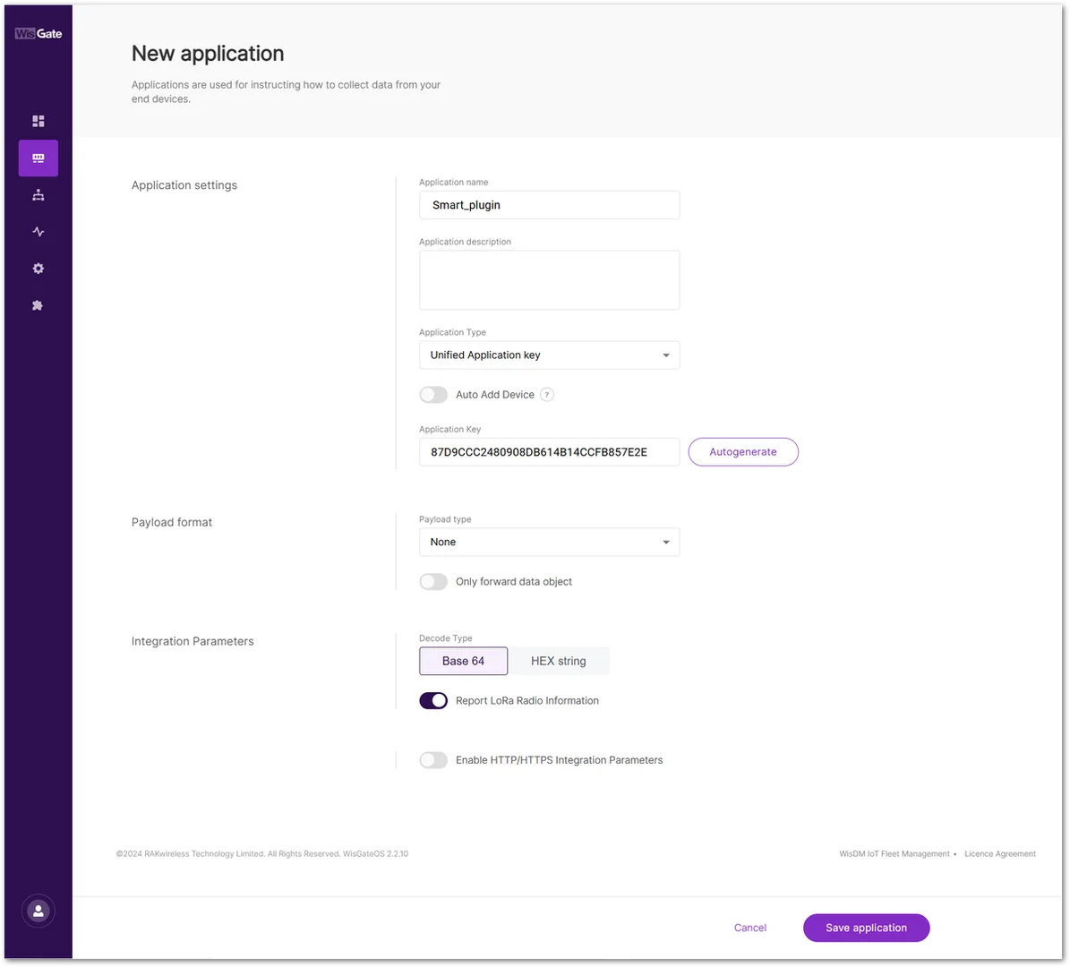 Figure 1: Create an application
- Application Name: Enter a name for the application.
- Application Description: Optionally, provide a brief description of the application.
- Application Type: Select the appropriate type from the drop-down menu.
- Unified Application Key: All devices will use the same application key.
- Separate Application keys: Each device uses its own App Key (entered during device registration)
- If a unified Application Key is used, ensure that it matches the AppKey configured on the RAK9105U.
- If Auto Add Device is enabled, also ensure that the Application EUI matches the RAK9105U.
- Click Save application.
Register the RAK9105U
If Auto Add Device is enabled, the RAK9105U can be added automatically after the Network Server receives its join request.
Otherwise:
- Go to End devices.
- Click Add end device.
- Configure the device information settings.
- Activation Mode: Select OTAA.
- End Device (Group) Name: Enter the name of the device for identification.
- Class: Select Class C.
- LoRaWAN MAC Version: Select V1.0.3 for the device.
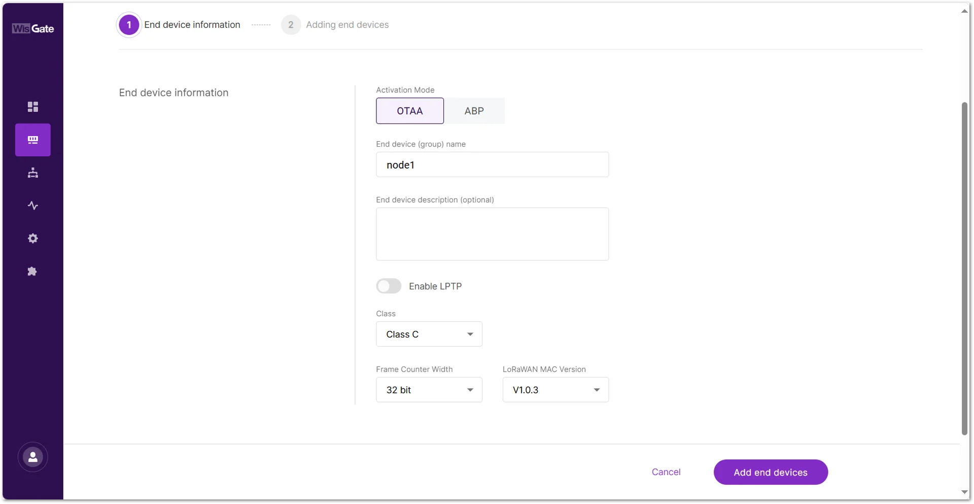 Figure 1: Add Device Manually
- In the next step, enter the End Device EUI (Main) (must match the one set in WisToolBox) and click Add to “End Devices List”.
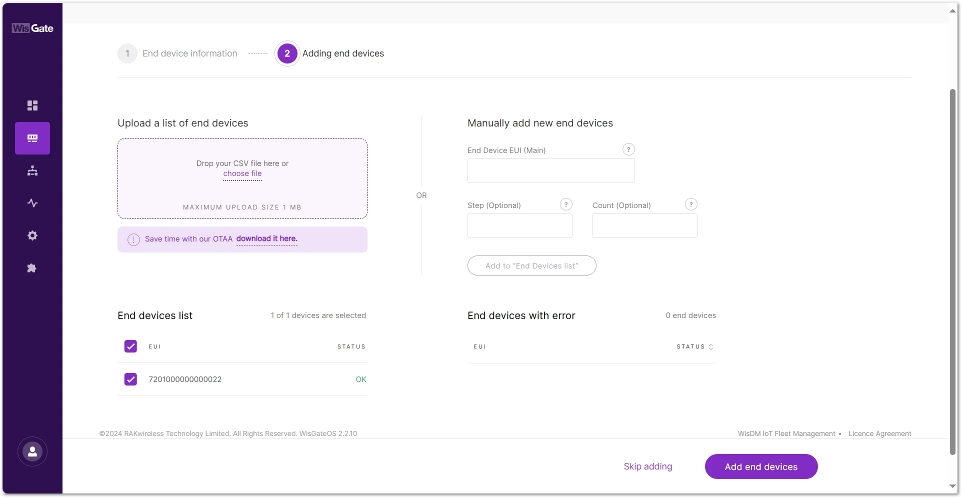 Figure 1: Enter the End Device EUI
 - Click Add end devices. Confirm and complete the device addition.
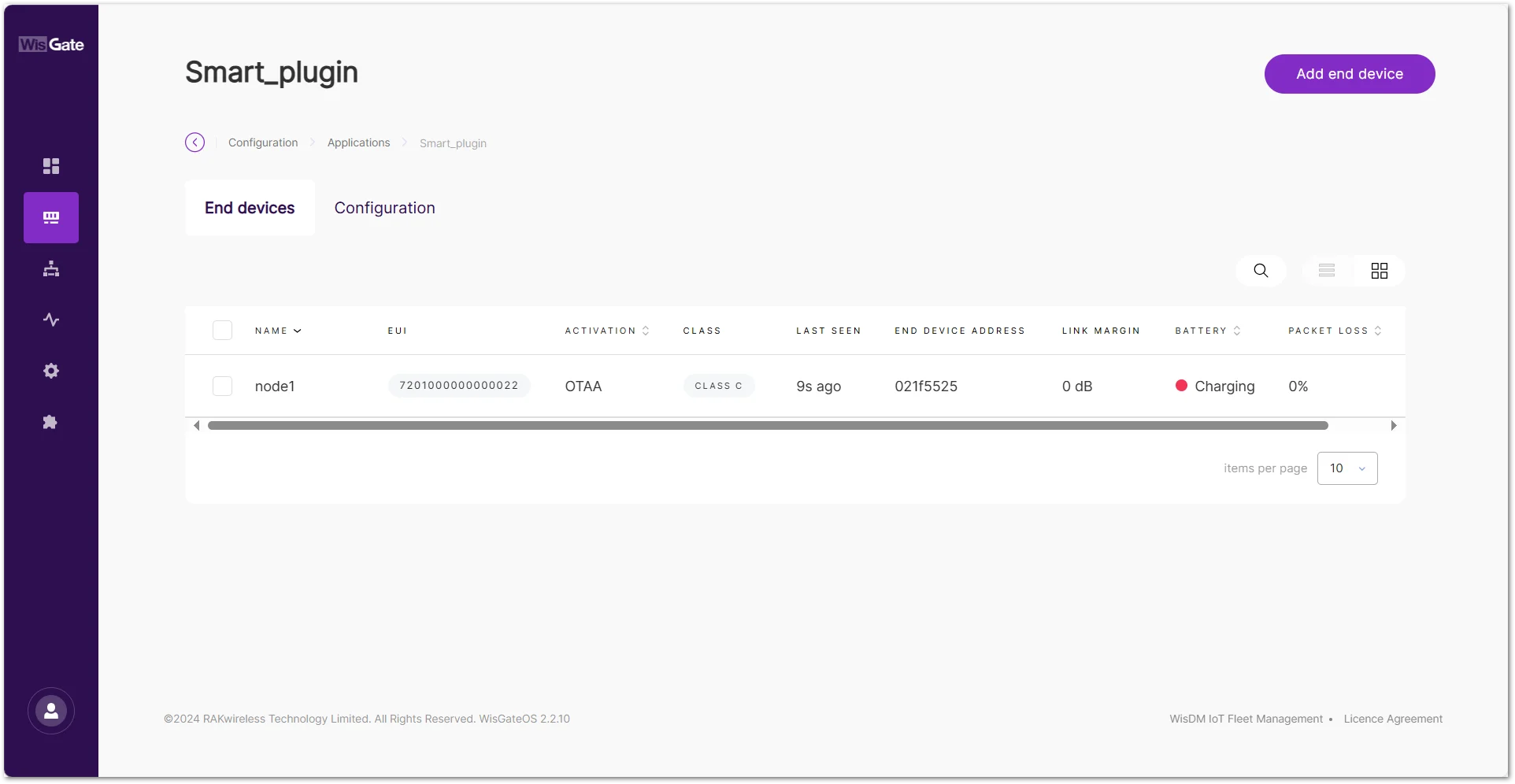 Figure 1: RAK9105U in the End Devices list
A recent Last Seen timestamp indicates that the Network Server has received data from the device.
The Things Stack
This section explains how to register the RAK9105U PowerLink on The Things Stack (TTN v3) using LoRaWAN OTAA activation, assuming the gateway is already deployed and connected to your TTN environment.
Create an Application
- Log in to The Things Stack Console.
- Go to Applications.
- Click Add Application.
- Enter the required application information.
- Click Create Application.
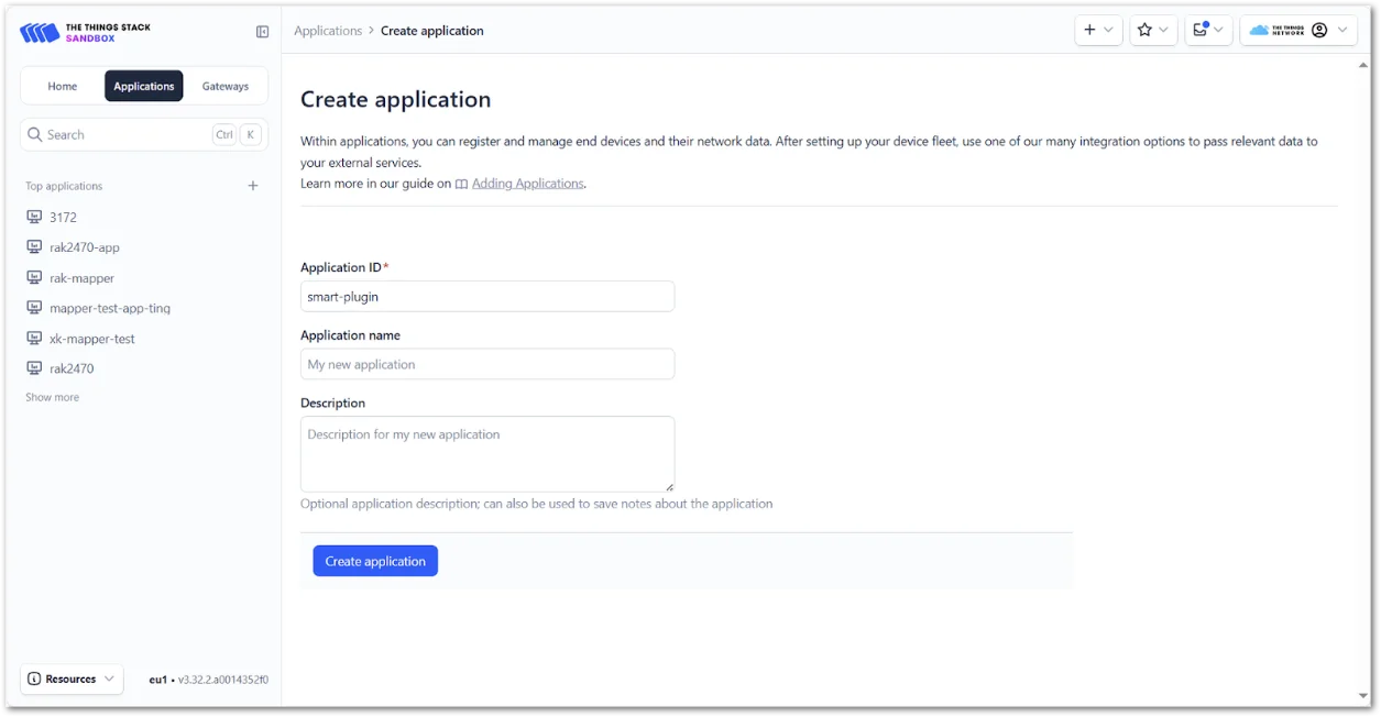 Figure 1: Create an application in The Things Stack
Register the RAK9105U
- Open the application.
- Click Register end device.
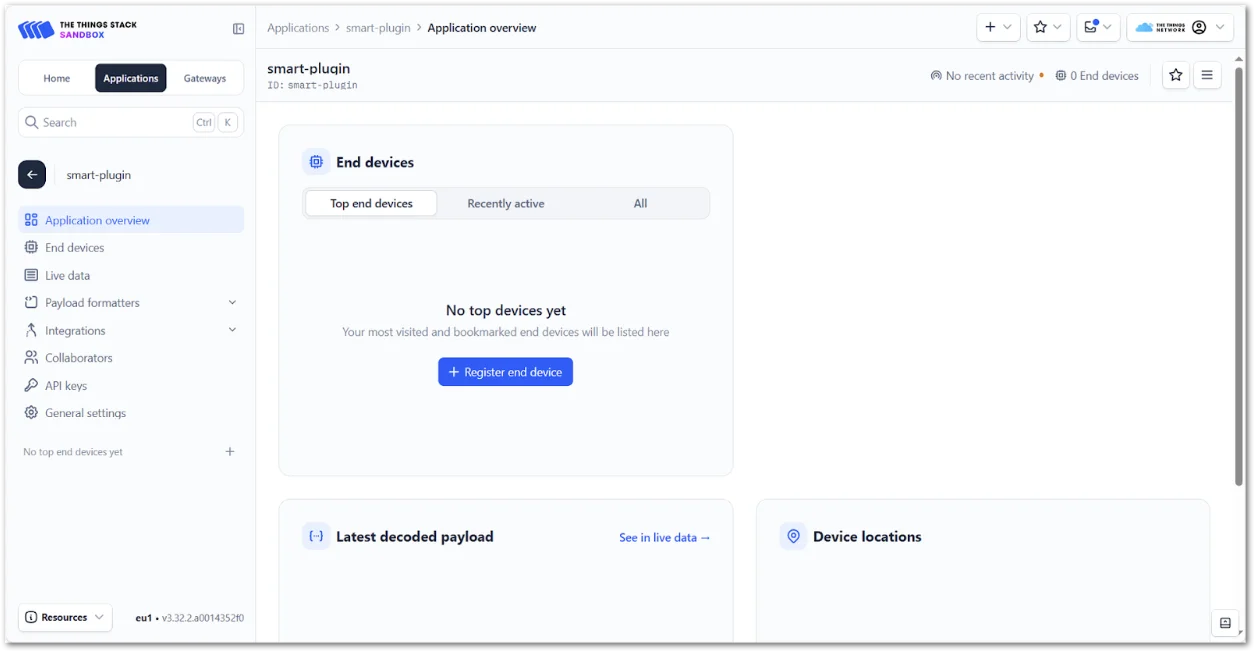 Figure 1: Register end device on TTN
 - Configure General Parameters
- Input Method: Select Enter end device specifics manually.
- Frequency Plan: Match your gateway’s region (e.g., EU868)
- LoRaWAN Version: Select 1.0.3
- JoinEUI: Enter the value that matches your RAK9105U configuration
- After confirming the JoinEUI, proceed to fill in:
- DevEUI: Same as configured on the RAK9105U
- AppKey: Must match the value set on the RAK9105U (or auto-generated during setup)
- End device ID: Enter a unique identifier (e.g., my-device)
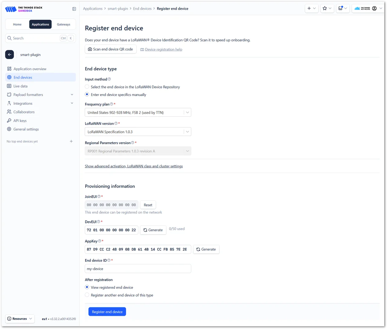 Figure 1: End Device Parameters
- Click Register end device to complete.
After the device joins, verify that recent activity appears in the console.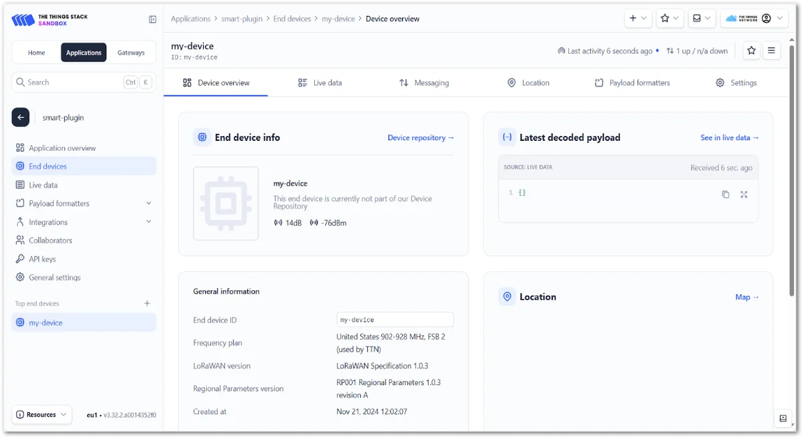 Figure 1: RAK9105U activity in The Things Stack
ChirpStack v4
This section explains how to register the RAK9105U PowerLink on ChirpStack v4 using OTAA activation, assuming that your LoRaWAN gateway is already deployed and connected to a functioning ChirpStack server.
Create an Application
- In ChirpStack, go to Applications.
- Click Add application.
- Enter the application name and optional description.
- Click Submit.
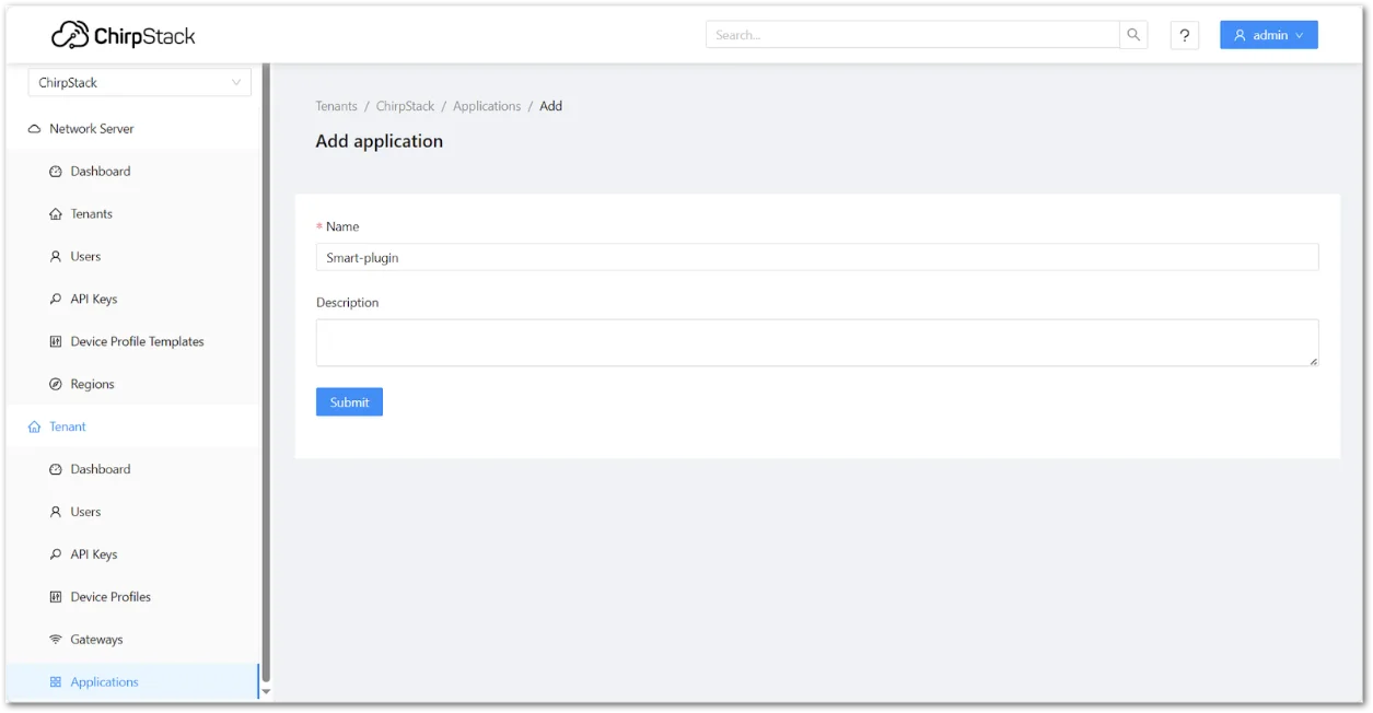 Figure 1: Create a ChirpStack application
Create a Device Profile
Before adding a device in ChirpStack v4, you need to create a Device Profile, which defines key configuration parameters for your LoRaWAN device.
The Device Profile ensures that ChirpStack correctly interprets how the device communicates with the network.
- Go to Device Profiles.
- Click Add device profile.
- Configure:
- Name: Enter a profile name (e.g., US915-OTAA-ClassC)
- Region: Select the region matching your gateway (e.g., US915, EU868)
- MAC version: LoRaWAN 1.0.3
- Regional parameters revision: Choose RP002-1.0.3
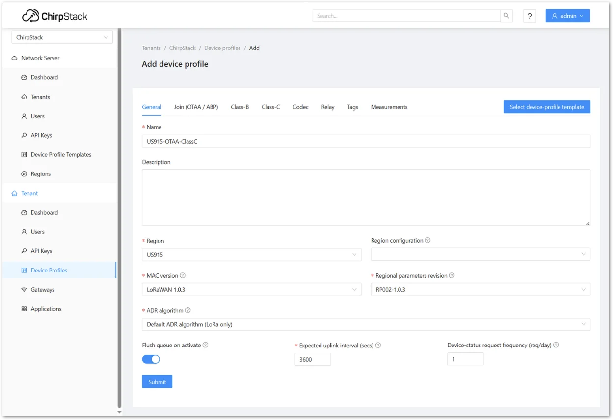 Figure 1: Configure the ChirpStack device profile
- In the Class-C tab, enable Device supports Class-C.
- Click Submit.
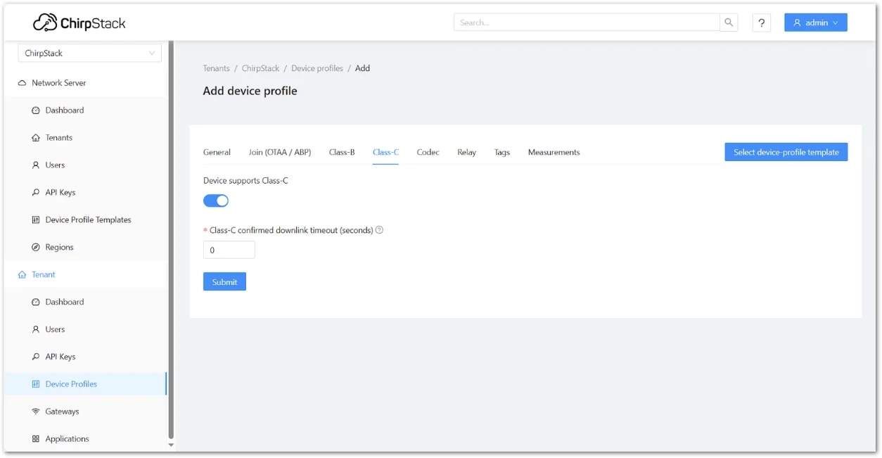 Figure 1: Enable Class C support
Register the RAK9105U
- Open the application.
- Click Add device.
- Configure:
- Name: Enter a name for your device
- Description: (Optional) Add a description to help identify the device
- Device EUI (EUI64): Same as configured on the RAK9105U
- Join EUI (EUI64): Same as configured on the RAK9105U
- Device profile: Select the one you just created
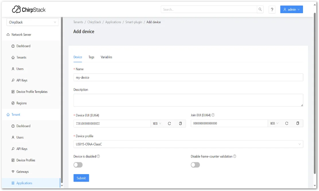 Figure 1: Register ChirpStack device details
- In OTAA Keys, enter the Application Key configured on the RAK9105U.
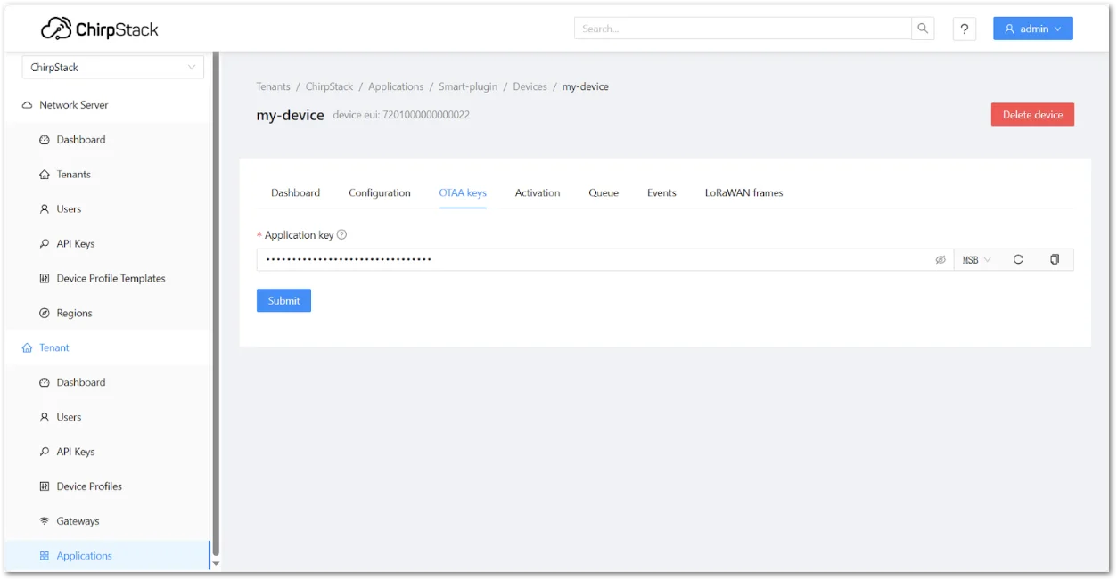 Figure 1: Configure the RAK9105U OTAA credentials
 - Click Submit.
After a successful join, verify that the device displays a recent Last Seen timestamp.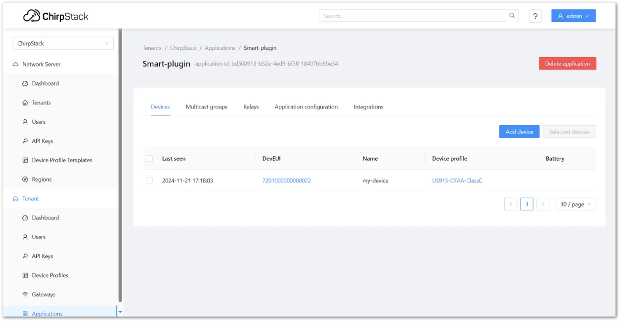 Figure 1: Submit ChirpStack device registeration
Hardware Installation
The hardware connection depends on whether the RAK9105U is used for Battery Plus monitoring only or for Battery Plus monitoring with remote power control.
Complete the LoRaWAN configuration and device registration before performing the final wiring.
Ensure that RAK Battery Plus is powered off before connecting or disconnecting any cables.
- Connect the 4-pin terminal block of the supplied power cable to the Input DC 12V RS485 interface on the RAK9105U according to the terminal markings.
NOTE
The
+and-terminals supply power from RAK Battery Plus to the RAK9105U, while theAandBterminals provide RS485 communication for reading Battery Plus operating data. - Connect the other end of the power cable to the 4-pin Output interface on RAK Battery Plus.
- (Optional) If remote power control is required, connect the target device to one of the controllable outputs on the RAK9105U:
- Output 2 - MCU-controlled DC output
- Output 3 - MCU-controlled 5 V USB Type-C output
Skip this step if the RAK9105U is used only for Battery Plus monitoring.
- Verify that all power and RS485 connections are secure and correctly wired.
- Press the ON/OFF switch on RAK Battery Plus to power on the system.
After startup, the RAK9105U reconnects to the configured LoRaWAN network if automatic joining is enabled and begins reporting Battery Plus operating data according to the configured uplink interval.
Verify Battery Plus Uplink Data
After the RAK9105U joins the LoRaWAN network, verify that uplink packets are received periodically by the Network Server.
When connected to RAK Battery Plus, the RAK9105U can report Battery Plus operating data collected through RS485 together with RAK9105U output interface status information.
For complete FPort definitions, payload formats, byte mappings, scaling rules, and Battery Plus field definitions, refer to the RAK9105U Uplink and Downlink Data Reference.
Verify Remote Power Control
git After uplink communication is confirmed, send a LoRaWAN downlink command from the Network Server to verify remote output control.
The basic output control commands are:
| Payload | Function |
|---|---|
0000 | Turn Output 3 (5 V USB Type-C) OFF |
0001 | Turn Output 3 (5 V USB Type-C) ON |
0100 | Turn Output 2 (DC output) OFF |
0101 | Turn Output 2 (DC output) ON |
For complete downlink command definitions and reporting commands, refer to the RAK9105U Uplink and Downlink Data Reference.
A connected device with internal capacitors or backup power storage may not power off immediately after the RAK9105U output is disabled.
Next Steps
Continue according to your application requirements:
- RAK9105U Uplink and Downlink Data Reference - Understand uplink payloads, Battery Plus operating data, output status, reporting intervals, and supported downlink commands.
- RAK9105U Application Integration - Integrate the RAK9105U with The Things Stack and Datacake for device data visualization and remote power control.


