RAK10730 WisMesh Pad Site Planner
Site Planner is a pre-deployment planning tool that simulates expected radio coverage based on the planned transmitter location, radio parameters, and environment settings, helping you determine suitable node locations before installation.
WisMesh Pad includes its own locally hosted version of the official Meshtastic Site Planner. For detailed information about its features and use, refer to the Meshtastic Site Planner documentation.
An internet connection is required to download terrain data when an area is accessed for the first time. Once the data is cached on WisMesh Pad, Site Planner can access that area offline.
Open Site Planner
-
From Mode Selection, select Check Your Deployment.
-
Select Site Planner from the navigation menu.
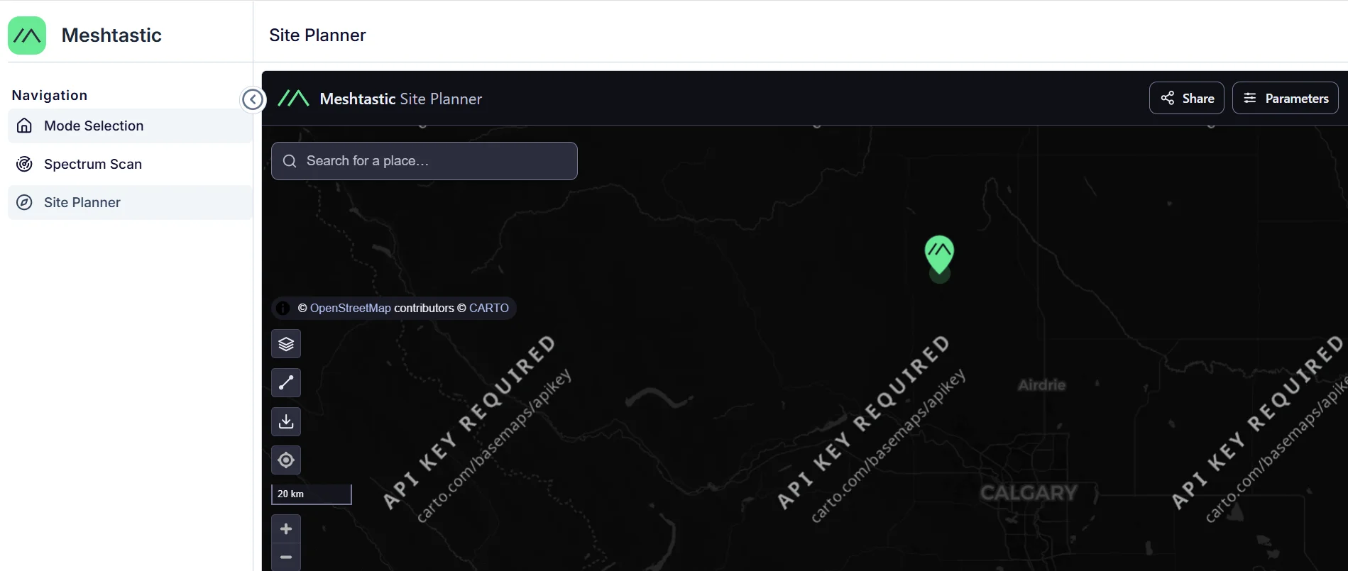 Figure 1: Site Planner workspace
The Site Planner workspace opens as an embedded page within WisMesh Pad.
Plan a Deployment Site
Configure the planned transmitter location and radio parameters, then run a simulation to evaluate the expected radio coverage.
- Select Device (Optional)
Select a supported device profile to automatically apply typical radio parameters. If no suitable device is available, select Custom / manual and configure the parameters manually. - Configure Radio Parameters
Configure the transmitter parameters based on the actual installation.
| Parameter | Description |
|---|---|
| Frequency | Sets the LoRa operating frequency used for the simulation. Configure it according to the deployment region. |
| Power | Sets the transmitter output power. Higher power provides stronger signals and wider coverage. |
| Height AGL | Sets the antenna height above ground level. Higher antenna placement can improve coverage. |
| Antenna Gain | Sets the transmitter antenna gain based on the antenna specification. |
- Run the Simulation
Click Run Simulation to generate the predicted Meshtastic network coverage result. - Review the Simulation Result
Review the predicted radio signal strength shown on the map, then adjust the planned transmitter location or radio parameters as needed. Use the simulation results to help determine suitable node locations.
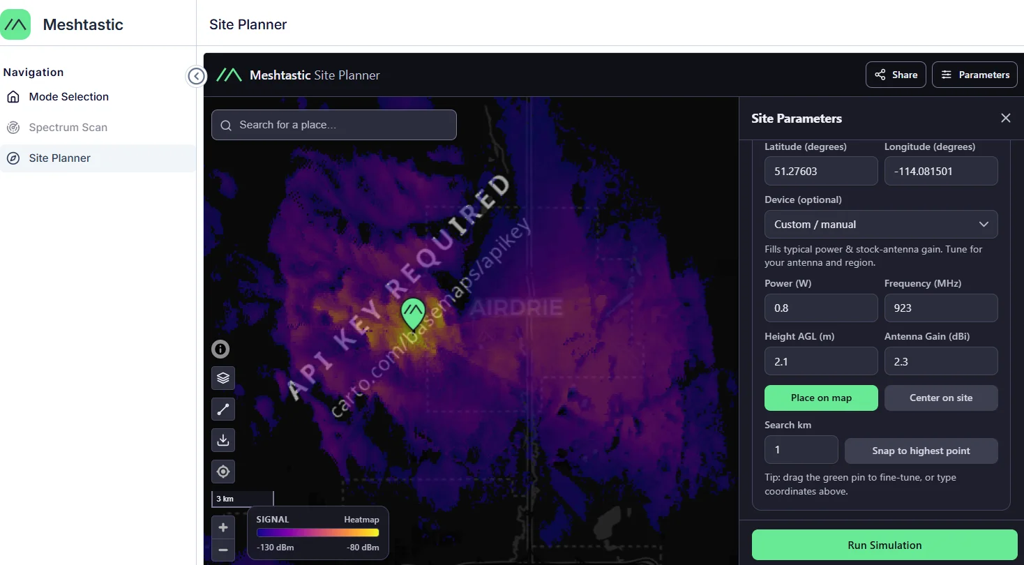 Figure 1: Site Planner deployment
Advanced Parameters
Site Planner provides additional parameters for advanced coverage analysis.
Receiver Parameters
Receiver parameters define the conditions required for receiving nodes to successfully receive signals.
| Parameter | Description |
|---|---|
| Sensitivity | Defines the minimum signal level required for communication. |
| Height AGL | Defines the installation height of receiving nodes. |
| Antenna Gain | Defines the receiver antenna gain. |
| Cable Loss | Defines signal loss caused by antenna cables or connectors. |
Environment Parameters
Environment parameters define the radio propagation conditions used for simulation. For most deployments, the default environment settings are recommended.
| Parameter | Description |
|---|---|
| Radio Climate | Defines the atmospheric propagation environment. |
| Polarization | Defines the antenna polarization direction. |
| Clutter Height | Defines surrounding obstacles that may affect signal propagation. |
| Ground Dielectric Constant | Defines ground reflection characteristics. |
| Ground Conductivity | Defines ground electrical properties. |
| Atmospheric Bending | Defines atmospheric refraction effects. |
Simulation Options
Simulation options control the simulation accuracy and calculation range.
| Parameter | Description |
|---|---|
| Situation Fraction | Defines the statistical confidence level for the coverage simulation. |
| Time Fraction | Defines the percentage of time the coverage condition is expected to be met. |
| Max Range | Defines the maximum simulation distance. |
| High Resolution Terrain | Uses higher resolution terrain data for more detailed simulation results. |
Display Options
Display options control how simulation results are visualized.
| Parameter | Description |
|---|---|
| Overlay Style | Selects the coverage visualization style, including Heatmap and Contours. |
| Minimum / Maximum dBm | Defines the RSSI range displayed on the coverage map. |
| Color Scale | Defines the color mapping used for coverage visualization. |
| Transparency | Adjusts the transparency of the coverage overlay. |
Point-to-point Link
Point-to-point Link analyzes the communication path between the transmitter and a target location based on terrain profile, line of sight, Fresnel clearance, and link margin.
Click Pick target on map and select a target location for point-to-point analysis.


